The Inventory Browser

Chapter 0

Introduction

Welcome to the CNC Simulator Pro User Guide, a comprehensive CNC simulator and CAD/CAM software suite.
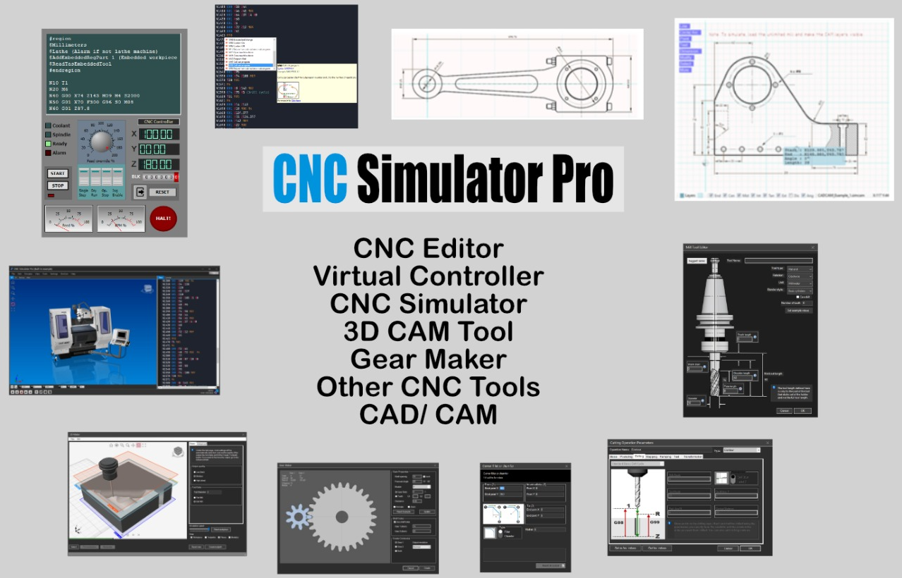
CNC Simulator Pro
CNC Simulator Pro - Main Interface

What is CNC Simulator Pro?

CNC Simulator Pro was designed to provide the CNC community with a contemporary CNC simulator containing the most common CNC machine types as virtual machines. The goal is to allow operators and students to safely test code in a 3D simulation before running it on real machines.

Important Note: The simulator in its standard configuration is not machine or controller specific. Due to the variety of CNC controllers with different G-code dialects, it will not be 100% compatible with your machine. Users are responsible for verifying code before running it on real machines.

Beyond Simulation

The software functions as much more than just a simulator - it includes:

  • Contemporary CAD/CAM system (SimCam)
  • Advanced CNC programming editor
  • 3D model milling software (3D Maker)
  • Gear creator (Gear Maker)
  • Training tool
  • And much more...

Sections in this Introduction

  • About CNC Simulator Pro - Detailed software overview
  • What is Needed? - System requirements and prerequisites
  • About Versions and Updates - Version information and how to update

0.1

About CNC Simulator Pro

CNC Simulator Pro is a comprehensive CNC simulator designed to provide the CNC community with a virtual environment for testing and learning CNC programming.

CNC Simulator Pro
CNC Simulator Pro - Main Interface

Software Overview

CNC Simulator Pro was developed to allow CNC operators, students, and enthusiasts to safely test G-code in a realistic 3D simulation before running it on real machines.

Key Features

  • Realistic 3D simulation - Visualize machining operations in real-time
  • Multiple virtual machines - Mills, lathes, multi-axis machines
  • Advanced CNC editor - Syntax highlighting, programming help
  • SimCam CAD/CAM - Integrated CAD/CAM system
  • 3D Maker - 3D model milling
  • Gear Maker - Gear creation

Important Note: The simulator in its standard configuration is not machine or controller specific. Users are responsible for verifying code before running it on real machines.

0.2

What is Needed?

This section describes the system requirements and prerequisites for running CNC Simulator Pro.

System Requirements

Component Minimum Recommended
Operating SystemWindows 7/8/10/11Windows 10/11 64-bit
ProcessorIntel Core i3 or equivalentIntel Core i5/i7 or higher
RAM4 GB8 GB or more
Disk Space500 MB1 GB
Graphics CardOpenGL 2.0OpenGL 3.3+ dedicated
Resolution1280x7201920x1080 or higher

Prerequisites

  • Microsoft .NET Framework 4.7.2 or later
  • Visual C++ Redistributable for Visual Studio 2019
  • Updated graphics drivers for OpenGL

0.3

About Versions and Updates

Information about CNC Simulator Pro versions and how to keep the software up to date.

Current Version

CNC Simulator Pro version 4.x is the latest major version of the software, with numerous improvements and new features.

Version History

  • Version 4.x - Current version with improved SimCam, new 3D Maker
  • Version 3.x - Introduction of SimCam and multi-language support
  • Version 2.x - Added lathe simulation and multi-axis machines
  • Version 1.x - Initial version with basic milling simulation

How to Update

To update CNC Simulator Pro:

  1. Visit the official website
  2. Download the latest version from the Download section
  3. Run the installation program
  4. Existing settings and files will be preserved
Chapter 1

Getting Started

This online guide will teach you how to use CNC Simulator Pro. It is assumed that you already have experience in CNC programming.

CNC Simulator Pro
CNC Simulator Pro - Main Interface

Chapter Overview

In this chapter you will learn:

  • 1.1 How to Control the 3D View - Navigation and control of the three-dimensional view
  • 1.2 Controlling the Simulation - How to start, stop, and control simulations
  • 1.3 Virtual Machines - The different types of virtual CNC machines available
  • 1.4 File Browsers - How to navigate and manage CNC files
  • 1.5 Sample Demo CNC Files - Sample files to get started right away
  • 1.6 View Buttons - Controls to customize the view

Tip: If you are new to CNC programming, we recommend following this section in the order presented to build a solid knowledge foundation.

1.1

How to Control the 3D View

Learn to navigate and control the 3D view in CNC Simulator Pro.

3D View
3D View Control

Mouse Controls

Action Control
Rotate viewRight-click + drag
PanMiddle-click + drag
ZoomMouse wheel
Zoom areaShift + selection rectangle

Preset Views

Use number keys for quick views:

  • 1 - Front view
  • 2 - Back view
  • 3 - Left side view
  • 4 - Right side view
  • 5 - Top view
  • 6 - Bottom view
  • 7 - Isometric view

1.2

Controlling the Simulation

Learn to control CNC simulation: start, pause, speed, and debug.

Simulation Controls

Use the simulation toolbar or keyboard shortcuts:

Action Shortcut Description
Start/PauseF5Start or pause simulation
StopF6Stop simulation and reset
Single StepF10Execute one block at a time
Speed ++Increase simulation speed
Speed --Decrease simulation speed

Simulation Modes

  • Normal - Simulate with visible material removal
  • Fast - Simulate quickly without detailed graphics
  • Debug - Step-by-step execution for analysis

1.3

Virtual Machines

Virtual Machines

CNC Simulator Pro includes a vast library of virtual machines that simulate different CNC machining center configurations.

File Format

Virtual machine files use the .cmachine extension and contain all the graphics and logic for the machine.

Loading a Machine

  1. Go to File → Load Machine
  2. Or click the "Open machine" button in the toolbar
  3. Browse through available machine folders
  4. Select the desired machine

Available Machine Types

Type Description
3-axis MillsVertical and horizontal machining centers
4-5 axis MillsMachines with rotary axes
CNC Lathes2-axis lathes and lathes with Y-axis
Turn-MillsCombined turn-mill machines
Laser/PlasmaCutting machines

Unlimited Machines

For applications requiring extended ranges, special machines without 3D graphics are available:

  • UnlimitedMill - Mill with ±50,000 units range
  • UnlimitedLathe - Lathe with ±50,000 units range
  • HeidenUnlimited - Heidenhain controller with extended range
  • UnlimitedCutter - Cutting machine with extended range

Note: "Unlimited" machines have no 3D graphical representation but allow simulating programs with very large coordinates.

Machine Settings

Each machine has configurable parameters in Settings → Machine:

  • Axis limits
  • Maximum speeds
  • Accelerations
  • Spindle configuration

1.4

File Browsers

File Browsers

File browsers are specialized dialog windows for opening CNC files, machines, and SimCam files. They include preview capabilities to help identify files before opening them.

Main Features

Preview

When you want to open a CNC file, you can click on it to see a simplified preview of the tool paths. This allows you to visualize the content before actually opening the file.

Favorite Folders

The star button allows you to bookmark frequently accessed folders, streamlining navigation through the file system.

Information Panel

Below the preview, a panel displays relevant details about the selected item, such as machine specifications when browsing machines.

Browser Types

Type Use Preview
CNC FilesG-code programsTool paths
MachinesVirtual machinesMachine image + specs
SimCamCAD/CAM projects2D drawing

Demo Programs

CNC Simulator Pro includes numerous demo files for learning:

  1. Go to File → Open CNC Program → Demo Program
  2. Select a demo file
  3. Click Play to start the simulation

Demo programs demonstrate:

  • Sub-program calls
  • Macro programming
  • Tool radius compensation
  • Canned cycles
  • Special simulator commands

Tip: Reviewing demo programs and their comments is an excellent way to get to know the simulator and understand its features, as well as learning the fundamentals of CNC programming.

1.5

Sample Demo CNC Files

CNC Simulator Pro includes numerous sample CNC files to help you get started.

Where to Find Demo Files

Sample files are located in the Samples folder within the program installation directory.

Demo File Categories

  • Milling - 2D and 3D milling examples
  • Turning - Turning examples
  • Multi-axis - Examples for 4 and 5 axis machines
  • Macro - Macro programming examples

How to Open a Demo File

  1. Go to File → Open or press Ctrl+O
  2. Navigate to the Samples folder
  3. Select a .cnc file and click Open
  4. Press F5 to start simulation

1.6

View Buttons

View buttons allow you to customize the 3D view and control what is displayed.

Main Buttons

Button Function
GridShow/hide reference grid
AxesShow/hide coordinate axes
ToolShow/hide tool
PathShow/hide tool path
WorkpieceShow/hide workpiece
MachineShow/hide machine structure

Rendering Options

  • Wireframe - Show only model edges
  • Solid - Solid rendering with shading
  • Transparent - Semi-transparent rendering

Chapter 2

The CNC Editor

The CNC Editor is the heart of CNC Simulator Pro, where you write, edit, and manage your G-code programs.

CNC Editor
The CNC Editor with advanced syntax highlighting

Chapter Overview

The editor offers numerous features to make CNC programming more efficient:

  • Code Coloring - Syntax highlighting for G-codes, M-codes, and parameters
  • Programming Help - Informative pop-ups while writing code
  • Code Regions - Organize code into collapsible sections
  • Pause Points - Set breakpoints for debugging
  • Find and Replace - Advanced code search
  • Block Numbering - Automatic line numbering
  • Comments - Add notes and documentation to code
  • CNC Headers - Create standard program headers
  • Undo/Redo - Complete edit history
  • Convert - Convert between different formats and dialects
  • Runtime Mode - View program execution

Tip: Use keyboard shortcuts to speed up your work. Press F1 to see context help on any G or M code.

Main Shortcuts

Key Function
Ctrl+FFind
Ctrl+HReplace
Ctrl+ZUndo
Ctrl+YRedo
F5Start Simulation
F9Toggle Pause Point

2.1

Editor Overview

The CNC Editor is the primary interface for writing and modifying CNC code in CNC Simulator Pro.

CNC Editor
The CNC Editor interface

Key Features

The CNC editor includes built-in functions to assist you while coding. Recognized CNC codes will be colored, and pop-up lists will help you with useful information while writing.

Editor Features

  • Code coloring - Automatic syntax highlighting for G-codes, M-codes, and special commands
  • Programming help pop-ups - Contextual suggestions while typing
  • Code regions - Organize code into collapsible sections
  • Pause points - Set breakpoints for simulation debugging
  • Find and replace - Quickly search and modify code
  • Automatic block numbering - Automatically number code lines
  • Comments in code - Add notes and documentation
  • CNC headers - Create standardized program headers
  • Undo and redo - Complete edit history management
  • Convert - Convert between metric and imperial units
  • Runtime mode - View status during simulation

Tip: The editor automatically recognizes valid CNC codes and highlights them with different colors to facilitate reading and writing your program.

2.2

Code Coloring

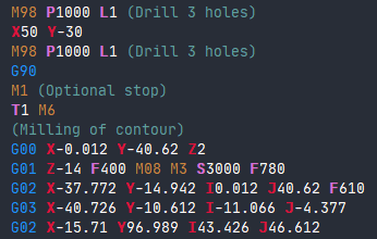
Code coloring is an editor feature that automatically highlights different types of CNC commands with distinct colors.

CNC Code Coloring
Example of code coloring in the CNC editor

Color Scheme

The CNC editor uses color coding to distinguish various program elements:

Element Color Example
G-codes Blue G00, G01, G02
M-codes Brown/Yellow M03, M05, M30
Special $-commands Light Blue $AddTool, $AddPart
Comments and strings Green (Comment)
G-codes in Blue
G-codes highlighted in blue

Performance Considerations

Note: Very large programs, such as those used for 3D Printing, will not be colored as it would slow down the editor.

Automatic coloring helps to:

  • Quickly identify different command types
  • Spot syntax errors
  • Improve program readability
  • Distinguish between code and comments

Related Sections

2.3

Programming Help Pop-ups

Programming help pop-ups provide intelligent assistance while you write CNC code in the editor.

How They Work

The editor displays intelligent pop-ups while you write to facilitate the programming process:

Code Lists

When typing specific characters, the editor displays relevant lists. For example, typing "G" shows a list of available G-codes.

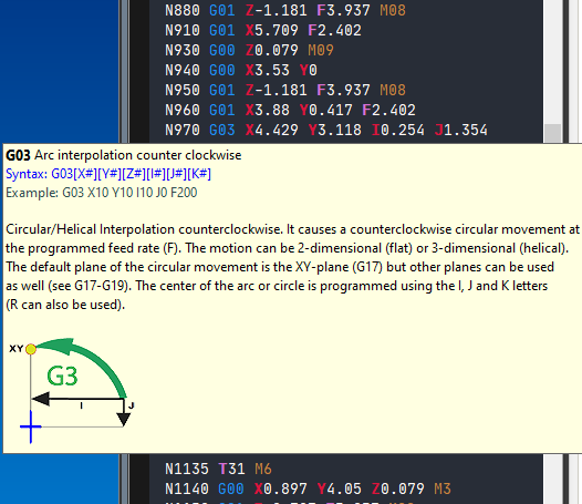
Help Tooltips

When entering a recognized G-code, it will show a help tooltip window explaining the code.

Navigation Methods

  • Arrow keys - Navigate up and down lists
  • Mouse - Click to select codes and preview tooltips
  • Enter or Tab - Inserts selected codes into the editor

Supported Code Types

The pop-up system works with:

  • G-codes
  • M-codes
  • $-codes (special commands)
  • Tools
  • Special commands like $AddRegPart and $AddEmbeddedRegPart

Workpiece Offset Assistance

When using codes G54-G59, the editor will help you by showing the workpieces offset values after the code.

Hover Information

Showing the tooltips while the mouse hovers over a recognized code provides additional context without active selection.

Purpose: The intelligent editor aims to help the user quickly find the codes they want to use.

2.4

Code Regions

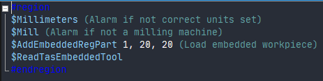
Code regions are special editor features that enable collapsible sections within CNC code.

Overview

The special editor codes #region and #endregion are used to create collapsible regions in the text.

Syntax

#region Region Name
G00 X0 Y0 Z10
G01 Z-5 F100
G01 X50 Y50
G00 Z10
#endregion

Functionality

Collapsing Regions

You can click the minus (-) symbol adjacent to the #region command to hide the section.

Expanding Regions

Clicking the plus (+) sign next to three dots will reveal a collapsed region.

Preview Feature

Hovering the mouse cursor over the three dots displays a preview of the hidden content without fully expanding it.

Practical Application

Note: SimCam automatically generates these commands for initial simulator settings, so that they can be easily hidden during a simulation.

Code regions are useful for:

  • Organizing long programs into logical sections
  • Hiding initial configurations during simulation
  • Improving code readability
  • Grouping related operations

2.5

Pause Points

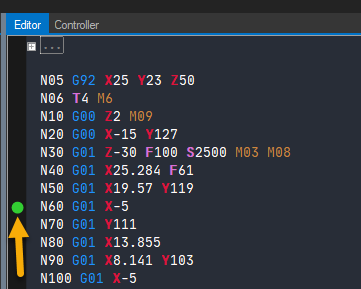
Pause points are small green dots in the editor margin that allow you to pause the simulation at specific points in the program.

Overview

Pause points are small green dots in the editor margin that are used to make a pause during the simulation.

Pause Points
Pause points in the editor margin

Setting Pause Points

You can add or remove pause points through a simple clicking mechanism. The process involves clicking on the margin area next to the code block where you want the simulation to pause.

Resuming Simulation

Once the simulation reaches a pause point, you have three options to continue:

  1. Play button - Click the play button to resume simulation
  2. Fast forward button - Click to advance quickly
  3. Single-step button - Click to execute one instruction at a time

Using Pause Points

Pause points are useful for:

  • Debugging CNC programs
  • Verifying tool position at specific points
  • Step-by-step analysis of complex operations
  • Training and demonstration

Tip: The visual indicator (green dots in the margin) makes pause points easy to identify within the editor interface during CNC code development and testing.

2.6

Find and Replace

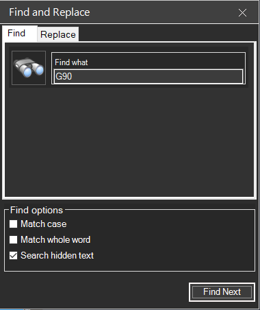
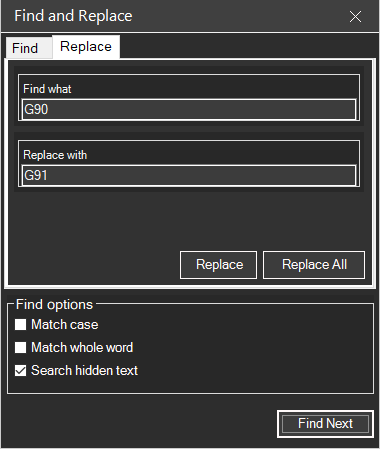
The Find and Replace function allows you to quickly search and modify text in your CNC program.

Find and Replace Dialog
Find and Replace dialog window

2.6.1 Access Methods

The Find and Replace dialog can be opened via:

  • Keyboard shortcut: CTRL + F
  • Menu navigation: Edit → Find and Replace

2.6.2 Find Features

Users can search for text by entering it in the "Find what" textbox and clicking Find Next. The search includes three optional parameters:

Search Options

Option Description
Match case If this option is checked, the search function will only find the text with the exact same case. For instance, "G90" and "g90" are treated as different.
Match whole word If this option is checked, the search function will only find whole words that match your search string. This prevents partial matches like finding "G9" within "G90".
Search hidden text If this option is checked, the search will include collapsed regions (see Code Regions).
Replace Tab
Replace tab for text substitution

2.6.3 Replace Features

The Replace tab allows users to perform text substitution:

  • Replace - Replace individual instances by clicking Find Next followed by Replace
  • Replace All - Replace all occurrences using the Replace All button

Tip: Use "Replace All" with caution, especially when modifying G or M codes, as it might affect unintended parts of the program.

Related Sections:

2.7

Automatic Block Numbering

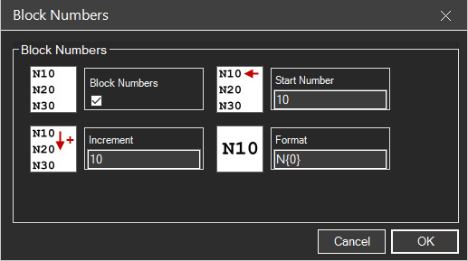
Automatic block numbering allows you to automatically add or renumber block numbers in your CNC program.

Block Numbers Dialog
Block Numbers dialog with configuration options

2.7.1 Accessing the Feature

To use automatic block numbering:

  • Press CTRL + B
  • Or navigate to Edit → Block Numbers in the menu

2.7.2 Basic Functionality

The feature allows users to add (or renumber) block numbers to your program by enabling the Block Numbers option and specifying parameters.

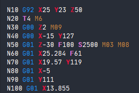
Code with block numbers
CNC code with block numbering applied

2.7.3 Configuration Options

Users must enter:

Parameter Description
Start Number The beginning value for block numbering (e.g., 10)
Increment The step value between consecutive block numbers (e.g., 10)

After setting these values, click OK to apply the numbering.

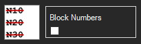
Removing block numbers
Checkbox deselected to remove block numbers

2.7.4 Managing Block Numbers

  • Adding/Renumbering - Repeat the process if blocks are deleted or added to the program
  • Removing - Open the Block Numbers dialog, deselect the Block Numbers checkbox, and click OK

2.7.5 Advanced Formatting

The dialog includes a format option for customizing number appearance. While the default format typically suffices, users can enter "formatting codes" to adjust the display style.

Format option
Format field for customizing block number appearance

Example: With Start Number = 10 and Increment = 10, blocks will be numbered N10, N20, N30, N40, etc.

Related Sections:

2.8

Comments in Code

Comments in code allow you to add notes and documentation to your CNC program without affecting the simulation.

Comments in CNC code
Example of comments in CNC code

2.8.1 Two Comment Methods

Parentheses Comments

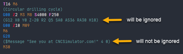
The primary approach involves placing comments within parentheses. CNC codes inside the parentheses will be ignored by the CNC Simulator Pro interpreter.

G00 X0 Y0 (Rapid move to origin)
G01 Z-5 F100 (Plunge cut)
Parentheses comments
Comments added using parentheses

Note: CNC Simulator Pro-specific $-commands will still be processed even when inside parentheses.

Semicolon Comments

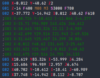
An alternative method uses semicolons, which is commonly used to comment out whole sections of blocks.

; This is a full line comment
; The code below is disabled:
; G00 X50 Y50
Semicolon comments
Comments added using semicolons

2.8.2 Selecting and Managing Comments

Block selection
Selecting multiple blocks in the editor

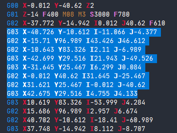
To comment out multiple blocks:

  1. Select them in the editor using Shift + Arrow keys or mouse dragging
  2. Selected blocks display in blue
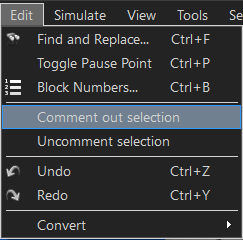
  3. Access the Edit menu and choose Comment out selection
Commented blocks
Commented code blocks

To restore commented code:

Select the blocks and use Uncomment selection from the Edit menu.

Usage: This feature allows developers to efficiently disable sections of CNC code without deleting them, facilitating testing and code organization.

Related Sections:

2.9

Create CNC Headers

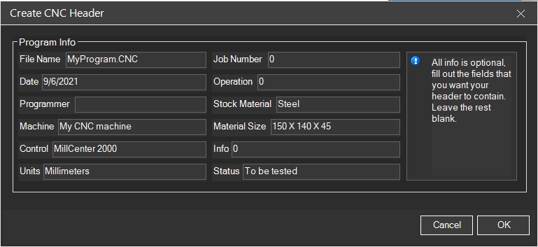
The Create CNC Header function allows you to automatically generate standardized headers for CNC programs.

Create CNC Header Dialog
Dialog for creating CNC headers

2.9.1 Overview

CNC Simulator Pro includes a "Create CNC Header" function that allows users to automatically generate headers for their CNC programs.

2.9.2 How to Create Headers

To access this feature, users should navigate to Tools → Create CNC Header from the main menu. This opens a dialog box where users can input their desired information.

2.9.3 Process

  1. Open the dialog from Tools → Create CNC Header
  2. Fill out the fields with the information you want in the header
  3. Click OK
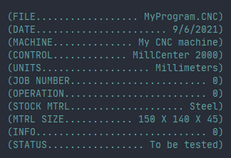
  4. The header will be automatically created for you

2.9.4 Typical Header Fields

  • Program name
  • Creation date
  • Author / Programmer
  • Part description
  • Revision number
  • Material
  • Additional notes
Generated CNC header
Automatically generated CNC header in code

Header Example

(====================================)
(  PROGRAM: BRACKET_001             )
(  DATE: 2024-01-15                 )
(  PROGRAMMER: J. Smith             )
(  MATERIAL: Aluminum 6061          )
(  REVISION: 1.0                    )
(====================================)

Benefits: The tool streamlines the header creation process by automating generation based on user-provided details, eliminating the need for manual coding of this standard program component.

Related Sections:

2.10

Undo and Redo

The Undo and Redo functions allow you to manage the edit history in the CNC editor.

2.10.1 Keyboard Shortcuts

Action Shortcut
Undo CTRL + Z
Redo CTRL + Y

2.10.2 Overview

If you do an edit by mistake, like erasing a big part of the program, you can always undo the change by pressing CTRL + Z on the keyboard.

In addition to reversing edits, users have the ability to restore previously undone actions through the redo function using CTRL + Y.

2.10.3 Menu Access

Both undo and redo operations are accessible through the Edit menu in the application interface, providing an alternative to keyboard shortcuts for users who prefer menu-based navigation.

Tip: The undo history is unlimited during the current session. You can undo all changes made since opening the file.

Related Sections:

2.11

Convert

The Convert function allows you to convert numbers between inches and millimeters and vice versa.

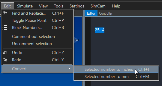
Convert Function
Unit conversion menu in the CNC editor

2.11.1 Functionality

The feature enables users to convert numbers from inches to millimeters and vice versa. To use it, you must first select the number you wish to convert in the editor, then access the Convert menu option.

2.11.2 Available Conversions

From To Formula
Inches Millimeters mm = in × 25.4
Millimeters Inches in = mm ÷ 25.4

2.11.3 How to Use

  1. Select the number in the editor you want to convert
  2. Navigate to Edit → Convert
  3. Choose the conversion direction
  4. The selected number will be replaced with the converted value

Example

; Before (inches):
G01 X1.0 Y0.5 F10

; After conversion (millimeters):
G01 X25.4 Y12.7 F254

Tip: Remember to also change the G20/G21 code when converting an entire program between unit systems. See G20-G21 Unit Selection.

Related Sections:

2.12

Runtime Mode

Runtime mode is the editor state during simulation execution, with specific visual indicators.

Editor in runtime mode
CNC editor in runtime mode during simulation

2.12.1 What It Is

Runtime mode is activated when you start a simulation in the CNC editor. The interface shifts to a read-only state during simulation execution, preventing program modifications.

2.12.2 Visual Indicators

During Simulation

During runtime (simulation is running), the background color of the editor changes slightly to indicate that it is in runtime mode. A gray line marks the current block being processed.

Error indicator
Error visual indicator with red wavy line

Error State

If the interpreter detects an error, you will see an alarm message and the editor will go back to normal mode, allowing edits. The problematic block receives a red wavy line so you can easily find it and correct the error.

Interrupted execution
Interrupted execution indicator with yellow square

Interrupted Execution

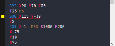
If you stop the execution (simulation) of a CNC program before it is done, a yellow square symbol indicates the last executed block.

2.12.3 State Summary

State Indicator Editing Allowed
Running Different background + gray line on current block No
Error Red wavy line on error block Yes
Interrupted Yellow square on last block Yes

Note: In runtime mode, the editor becomes read-only - you cannot make edits while simulation is active. Only errors force the system back to normal editing mode.

Related Sections:

Chapter 3

Simulation Tutorials

The Simulation Tutorials will guide you step by step through creating and simulating CNC programs for milling, turning, and multi-axis machining.

Simulation Tutorial
Simulation of a milling program

Available Tutorials

  • Milling Tutorial - Learn the basics of CNC milling with practical examples
  • Turning Tutorial - Discover how to program turning operations
  • Multi-axis Tutorial - Advanced techniques for 4 and 5 axis machining

Tip: Complete the tutorials in the suggested order to progressively build your skills.

3.1

Milling Tutorial

This tutorial will guide you through creating your first CNC milling program in CNC Simulator Pro.

Milling Tutorial
Simulation of a milling program

Preparation

Before starting, make sure to:

  • Select a milling machine from the inventory browser
  • Set up an appropriate workpiece
  • Configure the necessary tools

Step 1: Open a New Program

Create a new CNC file and start with the program header:

O0001 (MILLING TUTORIAL)
(T1 = END MILL D10)
G21 G17 G40 G49 G80 G90  ; Initialization

Step 2: Set Up the Tool

Select the tool and set the spindle speed:

T1 M6                    ; Tool change
S3000 M3                 ; Spindle 3000 RPM CW
G43 H1 Z50               ; Length compensation

Step 3: Machining Movements

Execute cutting movements to create a simple pocket:

G0 X0 Y0                 ; Rapid positioning
G0 Z5                    ; Approach
G1 Z-5 F100              ; Plunge
G1 X50 F200              ; Linear cut
G1 Y50
G1 X0
G1 Y0
G0 Z50                   ; Retract
M5                       ; Spindle stop
M30                      ; End program

Step 4: Run the Simulation

Press the Play button to start the simulation and observe the tool path in the 3D view.

Tip: Use the speed control buttons to slow down the simulation and better observe the movements.

Next Steps

After completing this basic tutorial, explore:

3.2

Turning Tutorial

This tutorial will guide you through creating your first CNC turning program.

Turning Tutorial
CNC lathe with mounted workpiece

Preparation

Before starting:

  • Select a lathe from the inventory browser
  • Set up a cylindrical workpiece
  • Configure the turning tools

Lathe Coordinate System

In CNC lathe:

  • X = diameter (or radius, depending on configuration)
  • Z = longitudinal axis (workpiece length)

Example: Facing and Roughing

O0001 (TURNING TUTORIAL)
(T1 = ROUGHING TOOL)
G21 G18 G40 G80 G90      ; Lathe initialization

T1 M6                    ; Tool change
G97 S1500 M3             ; Spindle 1500 RPM
G0 X52 Z2                ; Positioning

; FACING
G1 X-1 F0.2              ; Face to center
G0 Z2 X50

; DIAMETER ROUGHING
G71 U2 R1                ; Roughing cycle
G71 P10 Q20 U0.5 W0.1 F0.25
N10 G0 X20               ; Profile start
G1 Z0 F0.15
G1 X30 Z-10              ; Taper
G1 Z-30                  ; Cylinder
N20 X52                  ; Profile end

G0 X100 Z50              ; Retract
M5
M30

Turning Cycles

G70-G76 cycles simplify common operations:

  • G70: Finishing cycle
  • G71: Longitudinal roughing cycle
  • G72: Face roughing cycle
  • G73: Pattern repeat cycle
  • G76: Threading cycle

Tip: Use G96 for Constant Surface Speed (CSS) which maintains uniform surface velocity.

3.3

Multi-axis Tutorial

This tutorial introduces multi-axis machining techniques (4 and 5 axes) in CNC Simulator Pro.

Multi-axis Machine
5-axis machining center

Axis Configuration

In addition to the three linear axes (X, Y, Z), multi-axis machines include:

  • 4th Axis (A or B): Rotation around X or Y
  • 5th Axis (C): Rotation around Z

Example: 4th Axis Machining

O0001 (4TH AXIS EXAMPLE)
G21 G17 G40 G49 G80 G90
T1 M6
S5000 M3

G0 X0 Y0 Z50 A0          ; Initial position with 4th axis

; Machining on 4 faces (every 90°)
#1 = 0
WHILE [#1 LT 360] DO1
  G0 A#1
  G0 Z5
  G1 Z-2 F100
  G1 X30 Y0 F300
  G1 X30 Y30
  G1 X0 Y30
  G1 X0 Y0
  G0 Z50
  #1 = #1 + 90
END1

G0 A0 Z100
M30

Simultaneous 5-Axis Machining

In simultaneous 5-axis machining, all axes move together to maintain optimal tool orientation relative to the surface.

Advantages

  • Access to complex geometries
  • Better surface finish
  • Reduced setups
  • Shorter tools = greater rigidity

Warning: Multi-axis programming requires special attention to collisions. Always use simulation before running on real machines.

Chapter 4

The Inventory Browser

The Inventory Browser allows you to manage all available resources: machines, tools, and workpieces.

Inventory Browser
The Inventory Browser with resource categories

Inventory Sections

  • Inventory Overview - General introduction to the inventory system
  • Machines Inventory - All available virtual machines
  • Tools Inventory - Complete tool library
  • Workpieces Inventory - Workpiece definitions

Tip: You can create custom tools and save them in your library for future reuse.

4.1

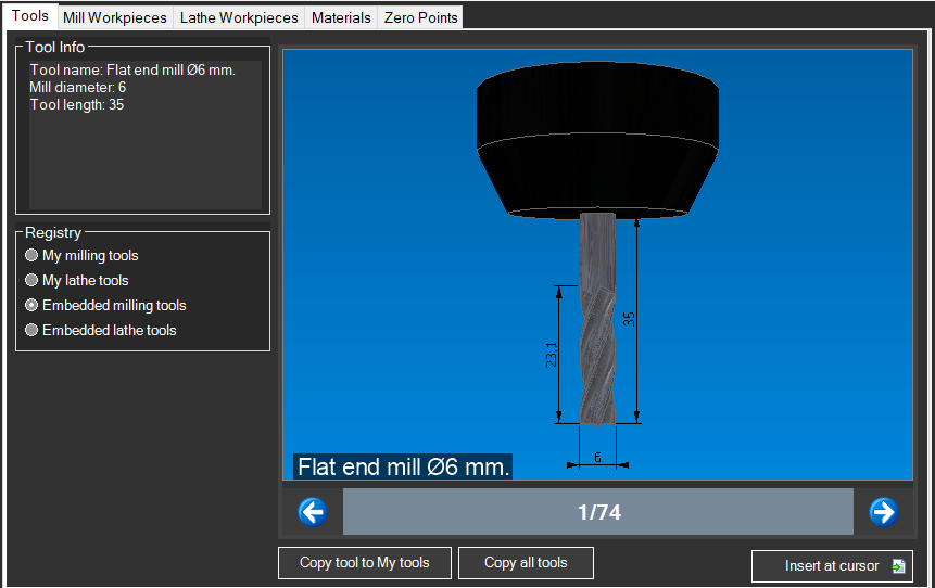
Tools

The Tools tab in the Inventory Browser contains the complete library of cutting tools for milling and turning.

Tool Library
The tool library in the Inventory Browser

Tool Categories

Milling Tools

  • End Mills - For contouring, facing, and grooving
  • Ball Nose Mills - For 3D surfaces and fillets
  • Flat End Mills - For pockets and flat surfaces
  • Bull Nose Mills - For fillets and corner rounding
  • Center Drills - For centering before drilling
  • Twist Drills - For standard holes
  • Taps - For internal threads
  • Reamers - For precision holes
Milling Tools
Milling tool selection

Turning Tools

  • External Tools - For cylindrical turning and facing
  • Boring Bars - For internal machining
  • Grooving Tools - For grooves and parting
  • Threading Tools - For external and internal threads
  • Parting Tools - For cut-off operations
Turning Tools
Turning operation tools

Adding a Tool

  1. Open the Inventory Browser (F4)
  2. Select the "Tools" tab
  3. Browse categories or use search
  4. Double-click a tool to add it to the turret
  5. Specify the slot number (T1, T2, etc.)

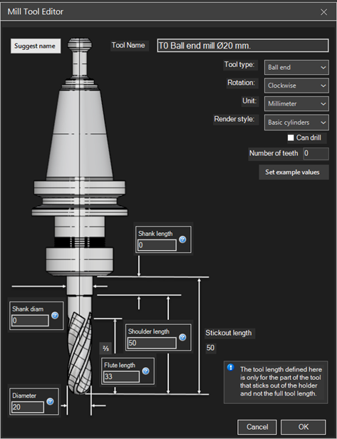
Tool Parameters

Each tool has configurable parameters:

  • Diameter - Tool diameter
  • Length - Total length or stick-out
  • Corner Radius - For bull nose mills or inserts
  • Number of Flutes - For feed rate calculations
  • Point Angle - For drills and turning tools

Tip: You can create custom tools with specific dimensions and save them to your personal library for reuse in future projects.

See Also

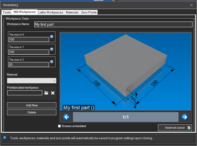
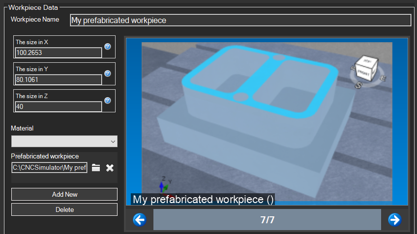
4.2

Mill Workpieces

Mill Workpieces define the shape and dimensions of raw material for milling operations.

Mill Workpieces
Mill workpiece selection in the Inventory Browser

Available Shapes

Rectangular Block

The most common shape for milling. Defined by three dimensions:

  • Width (X) - Dimension along the X axis
  • Depth (Y) - Dimension along the Y axis
  • Height (Z) - Dimension along the Z axis
Rectangular Block
Rectangular block configuration

Cylinder

For round parts to be machined on milling machines:

  • Diameter - Outer diameter of the cylinder
  • Height - Length of the cylinder

Disc

A cylinder with reduced height, ideal for:

  • Flanges and circular plates
  • Gears and sprockets
  • Covers and lids

Workpiece Setup

  1. Open the Inventory Browser (F4)
  2. Expand the "Mill Workpieces" section
  3. Select the desired shape
  4. Enter dimensions in the properties panel
  5. Double-click to load the workpiece
Workpiece Dimensions
Dimension configuration panel

Tip: Always set the raw stock slightly larger than the finished part for machining allowance.

Origin Positioning

The workpiece origin determines the program zero point:

  • Top center - Origin at center of top face (most common)
  • Corner - Origin at a workpiece corner
  • Geometric center - Origin at volume center

See Also

4.3

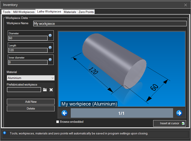
Lathe Workpieces

Lathe Workpieces define the shape and dimensions of raw material for turning operations.

Lathe Workpieces
Lathe workpiece selection in the Inventory Browser

Available Shapes

Cylindrical Bar

The standard shape for turning. Defined by:

  • Diameter - Outer diameter of the bar
  • Length - Total length of the workpiece
Cylindrical Bar
Cylindrical bar configuration

Tube

Hollow cylinder for tubular parts:

  • Outer diameter - OD of the tube
  • Inner diameter - ID of the tube (bore)
  • Length - Total length

Predefined Profile

Shapes with pre-defined external profile:

  • Pre-roughed parts
  • Castings or forgings
  • Semi-finished parts

Workpiece Setup

  1. Open the Inventory Browser (F4)
  2. Expand the "Lathe Workpieces" section
  3. Select the desired shape
  4. Enter dimensions (diameter, length)
  5. Double-click to load
Lathe Workpiece Setup
Configuration panel for lathe workpieces

Coordinate System

On the lathe, the origin is typically:

  • X - Radial axis (diameter or radius)
  • Z - Longitudinal axis (length)
  • Z origin - On the front face of the workpiece
  • X origin - On the center of rotation (spindle axis)

Tip: Always leave stock allowance on diameter and length for facing and finishing.

See Also

4.4

Materials

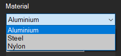
The Materials section allows you to assign material properties to your workpieces for more realistic simulation.

Materials Selection
Material selection panel in the Inventory Browser

Available Materials

Metals

  • Aluminum - Light gray, soft, easy to machine
  • Steel - Dark gray, durable
  • Stainless Steel - Silver, corrosion resistant
  • Brass - Golden yellow, good machinability
  • Copper - Reddish, high conductivity
  • Titanium - Metallic gray, lightweight and strong

Plastics

  • ABS - Black or white, impact resistant
  • Nylon - Cream white, self-lubricating
  • Delrin/POM - White, high precision
  • Polycarbonate - Transparent, durable
  • PTFE - White, low friction

Other Materials

  • Wood - Brown with grain
  • Graphite - Black, for electrodes
  • Foam - For models and prototypes

Assigning a Material

  1. Select the workpiece in the 3D view
  2. Open the Inventory Browser (F4)
  3. Go to the "Materials" section
  4. Double-click the desired material

Simulation Effects

The assigned material affects:

  • Visual appearance - Color and reflection in 3D view
  • Chip removal - Realistic machining visualization
  • Parameter suggestions - Recommended speeds and feeds

Note: Material selection is primarily for visualization. Cutting parameters should be verified with tool manufacturer specifications.

See Also

4.5

Zero Points

Zero Points define the coordinate system origins for the CNC program, allowing you to correctly position the workpiece relative to the machine.

Zero Points
Zero points configuration in the Inventory Browser

Fundamental Concepts

Machine Coordinate System

The Machine Coordinate System (MCS) is the absolute reference of the CNC machine:

  • Machine origin - Fixed point defined by manufacturer
  • Home position - Reference position after homing
  • Absolute coordinates - Measured from machine origin

Workpiece Coordinate System

The Workpiece Coordinate System (WCS) is the programming reference:

  • G54-G59 - Standard work offsets (up to 6)
  • G54.1 Pxx - Extended offsets (up to 99 or more)
  • Offset - Distance between machine origin and work origin

Setting Zero Points

In the Inventory Browser

  1. Open the Inventory Browser (F4)
  2. Go to the "Zero Points" section
  3. Select the coordinate system (G54, G55, etc.)
  4. Set the X, Y, Z coordinates
  5. Confirm with double-click
Origin Setup
Origin setup panel

Typical Positioning

Type Typical Position
Milling Center or corner of top surface
Turning Center of workpiece front face

Important: Ensure the program origin matches the origin set on the real machine before machining.

Tool Offset and Zero

Zero points work together with tool offsets:

  • Length offset (H) - Compensates tool length
  • Radius offset (D) - Compensates tool radius
  • Wear - Compensations for tool wear

See Also

Chapter 5

Settings

Settings allow you to customize CNC Simulator Pro according to your preferences and needs.

Settings Categories

  • General Settings - Language, units of measurement, application behavior
  • Machine Settings - Virtual machine configuration
  • Display Settings - Graphics appearance and 3D visualization
  • Simulation Settings - Simulation parameters and speed

Tip: Settings are automatically saved and maintained between sessions.
5.1

General Settings

General Settings

Configuration of CNC Simulator Pro general settings.

Accessing Settings

Menu Edit → Settings or F10

Language

CNC Simulator Pro supports multiple languages:

  • Italian
  • English
  • German
  • French
  • Spanish
  • And many more...

Units of Measure

Setting Options
Linear unitsMillimeters (mm) / Inches
Angular unitsDegrees / Radians
Speedmm/min, m/min, inch/min

Automatic Backup

  • Enable/disable automatic backup
  • Backup interval (minutes)
  • Destination folder
  • Maximum number of backups

Updates

  • Automatic update check
  • Update channel (stable/beta)

5.2

Machine Settings

Machine Settings

Configuration of virtual machine parameters.

Machine Selection

CNC Simulator Pro includes various virtual machines:

  • 3-axis Mill
  • 4-axis Mill
  • 5-axis Mill
  • 2-axis Lathe
  • Lathe with C-axis
  • Machining Center
  • Laser/Plasma Cutter
  • CNC Router

Machine Limits

Parameter Description
X TravelX-axis movement limit
Y TravelY-axis movement limit
Z TravelZ-axis movement limit
Max RPMMaximum spindle speed
Max FeedMaximum feed rate
RapidRapid speed (G0)

Controller Configuration

Select the G-code dialect compatible with your controller:

  • Fanuc
  • Siemens
  • Haas
  • Mazak
  • Heidenhain
  • Generic ISO

Note: Machine settings affect program validation and simulation behavior.

5.3

Display Settings

Display Settings

Customization of visualization and graphical interface.

3D View

Option Description
Render qualityLow/Medium/High
Anti-aliasingEdge smoothing
ShadowsEnable 3D shadows
ReflectionsMetallic reflections

Colors

Customize colors for:

  • Viewport background
  • Stock material
  • Machined part
  • Rapid path (G0)
  • Work path (G1/G2/G3)
  • Grid
  • Coordinate axes

Visible Elements

  • Grid - Show/hide reference grid
  • Axes - Show/hide XYZ axes
  • Toolpath - Path trace
  • Tool - 3D tool visualization
  • Spindle - Spindle visualization
  • Table - Work surface

Interface Theme

  • Light theme
  • Dark theme
  • Custom theme

Tip: Reduce render quality on less powerful computers to improve performance.

5.4

Simulation Settings

Simulation Settings

Content coming soon.

Chapter 6

Codes and Commands

Codes and Commands are the fundamental language of CNC programming. This section covers all supported G and M codes.

G Codes
G-code quick reference

Chapter Contents

  • G-Codes Overview - General overview of preparatory codes
  • G00-G03 - Basic movements (rapid, linear, arcs)
  • G17-G19 - Work plane selection
  • G40-G42 - Tool radius compensation
  • G54-G59 - Work coordinate systems
  • G70-G76 - Turning cycles
  • G80-G89 - Drilling cycles
  • M-Codes - Auxiliary functions (spindle, coolant, etc.)

Note: Codes may vary slightly between different CNC controllers. Always verify compatibility with your actual machine.

6.1

G-Codes Overview

G-Codes Overview

Content coming soon.

6.2

G00-G03 Basic Movements

G00-G03 Basic Movements

Content coming soon.

6.3

G17-G19 Plane Selection

G17-G19 Plane Selection

Content coming soon.

6.4

G40-G42 Tool Radius Compensation

G40-G42 Tool Radius Compensation

Content coming soon.

6.5

G54-G59 Work Coordinate Systems

G54-G59 Work Coordinate Systems

Content coming soon.

6.6

G70-G76 Turning Cycles

G70-G76 Turning Cycles

Content coming soon.

6.7

G80-G89 Drilling Cycles

G80-G89 Drilling Cycles

Content coming soon.

6.8

M-Codes

M-Codes

Content coming soon.

Chapter 7

Tools

The Tools section covers everything about tool management in CNC Simulator Pro.

Tool Management
CNC Simulator Pro tool library

Topics Covered

  • Tools Overview - Introduction to tool management
  • Milling Tools - End mills, drills, special tools
  • Turning Tools - Inserts, boring bars, parting tools
  • Tool Library - How to create and organize your library
  • Tool Offsets - Tool compensation configuration

7.1

Tools Overview

Tools Overview

Content coming soon.

7.2

Milling Tools

Milling Tools

Content coming soon.

7.3

Turning Tools

Turning Tools

Content coming soon.

7.4

Tool Library

Tool Library

Content coming soon.

7.5

Tool Offsets

Tool Offsets

Content coming soon.

Chapter 8

Serial Communication

Serial Communication allows you to connect CNC Simulator Pro to real CNC machines for program transfer.

Topics Covered

  • Serial Overview - Introduction to serial communication
  • Connection Setup - Setting up communication parameters
  • Data Transfer - Sending and receiving CNC programs

Warning: Always verify communication parameters with your CNC machine manual before making transfers.

8.1

Serial Overview

Serial Overview

Content coming soon.

8.2

Connection Setup

Connection Setup

Content coming soon.

8.3

Data Transfer

Data Transfer

Content coming soon.

Chapter 9

Helpers

Helpers are integrated utilities that facilitate calculations and common operations in CNC programming.

Helpers
Integrated calculators and tools

Available Tools

  • Arc Calculator - Calculate parameters for G02/G03 circular interpolations
  • Speed/Feed Calculator - Optimize cutting parameters
  • Thread Calculator - Parameters for threading cycles
  • Gear Maker - Generate programs for gears
  • 3D Maker - Create toolpaths from 3D models

Tip: Calculators automatically insert the generated code into the CNC editor.

9.1

Arc Calculator

Arc Calculator

Content coming soon.

9.2

Speed/Feed Calculator

Speed/Feed Calculator

Content coming soon.

9.3

Thread Calculator

Thread Calculator

Content coming soon.

9.4

Gear Maker

Gear Maker

Content coming soon.

9.5

3D Maker

3D Maker

Content coming soon.

Chapter 10

Custom Macro

Custom Macro (Macro B) extends CNC programming capabilities with variables, operators, and control structures.

Custom Macro
Example of parametric programming

Topics Covered

  • Macro Introduction - What is parametric programming
  • Variables - Local (#1-#33), common (#100-#199), and system variables
  • Operators - Arithmetic, logical operators and mathematical functions
  • Control Flow - IF/THEN/ELSE, WHILE/DO, GOTO
  • Practical Examples - Commented example programs

Tip: Macros allow you to create flexible and reusable programs for families of similar parts.

10.1

Macro Introduction

Introduction to Custom Macros

Custom Macros (also called Macro B or parametric programming) allow creating flexible CNC programs using variables, mathematical operations, and control structures.

Benefits of Parametric Programming

  • Reusable programs with variable dimensions
  • Reduced programming errors
  • Part families with a single program
  • Automatic calculations
  • Custom cycles

Basic Example

#1 = 50        ; Diameter
#2 = 30        ; Depth
#3 = [#1/2]    ; Radius (calculated)

G00 X#3 Y0 Z5
G01 Z-#2 F100
G02 X#3 Y0 I-#3 J0 F200
G00 Z5

Compatibility

Macro syntax varies between controllers (Fanuc, Haas, Siemens). CNC Simulator Pro primarily supports Fanuc syntax.

10.2

Variables

Macro Variables

Variables are fundamental elements of parametric programming and allow storing and manipulating numerical values.

Variable Types

Range Type Description
#1 - #33LocalArguments passed to macro (A=#1, B=#2, C=#3...)
#100 - #199CommonShared between programs, cleared on power off
#500 - #999PermanentRetained even after power off
#1000+SystemAxis positions, machine states, timers

Common System Variables

Variable Description
#5001-#5006Block end position (X,Y,Z,A,B,C)
#5021-#5026Current machine position
#5041-#5046Current work position
#3001Millisecond timer
#3002Hour timer
#4001-#4021Active modal G codes

Using Variables

; Assignment
#1 = 25.5          ; Direct value assignment
#2 = #1 * 2        ; Operation result assignment
#3 = [#1 + #2] / 2 ; Complex expression

; Use in movements
G1 X#1 Y#2 Z#3 F500

; Use in parameters
G81 X0 Y0 Z[-#4] R2 F#5

; Indirect variables
#[#10] = 100       ; #10 contains variable number
#11 = #[#10]       ; Reads variable indicated by #10

Empty Variable (#0)

Variable #0 is always empty and can be used to:

  • Check if an argument was passed
  • Skip optional parameters
IF [#1 EQ #0] THEN #1 = 10  ; If #1 empty, use default 10

Note: Variable ranges may vary between controllers. Always check your specific controller manual.

10.3

Operators

Macro Operators

Operators allow mathematical calculations, logical comparisons, and data manipulations in macros.

Arithmetic Operators

Operator Function Example
+Addition#1 = #2 + #3
-Subtraction#1 = #2 - #3
*Multiplication#1 = #2 * #3
/Division#1 = #2 / #3
MODModulo (remainder)#1 = #2 MOD #3

Mathematical Functions

Function Description Example
SIN[x]Sine (degrees)#1 = SIN[45]
COS[x]Cosine (degrees)#1 = COS[45]
TAN[x]Tangent (degrees)#1 = TAN[45]
SQRT[x]Square root#1 = SQRT[100]
ABS[x]Absolute value#1 = ABS[-5]
ROUND[x]Rounding#1 = ROUND[3.7]

Comparison Operators

Operator Meaning
EQEqual to (=)
NENot equal (≠)
GTGreater than (>)
GEGreater or equal (≥)
LTLess than (<)
LELess or equal (≤)

Logical Operators

  • AND: Logical AND
  • OR: Logical OR
  • XOR: Exclusive OR

Examples

; Calculate radius from coordinates
#10 = SQRT[[#1*#1] + [#2*#2]]

; Calculate angle
#11 = ATAN[#2]/[#1]

; Compound condition
IF [[#1 GT 0] AND [#1 LT 100]] GOTO 10

10.4

Control Flow

Control Structures

Control structures allow creating programs with decisions and repetitions.

IF...THEN...ELSE

Conditional execution:

; Simple IF
IF [#1 GT 0] THEN #2 = 1

; IF with GOTO
IF [#1 EQ 0] GOTO 100

; IF...THEN...ELSE (some controllers)
IF [#1 GT 0] THEN
  #2 = 1
ELSE
  #2 = -1
ENDIF

GOTO

Unconditional jump to a sequence number:

GOTO 100        ; Always jump to N100

N100 G0 X0 Y0

WHILE...DO...END

Loop with condition at start:

; Repeat while condition true
#1 = 0
WHILE [#1 LT 10] DO1
  G1 X#1 F500
  #1 = #1 + 1
END1

; Nested loops (DO1, DO2, DO3)
WHILE [#1 LT 5] DO1
  WHILE [#2 LT 5] DO2
    ; inner code
  END2
END1

Example: Circular Hole Pattern

; Parameters
#1 = 50      ; Circle radius
#2 = 8       ; Number of holes
#3 = 0       ; Start angle
#4 = -15     ; Depth

; Calculate angular step
#5 = 360 / #2

; Hole cycle
#6 = 0                          ; Counter
WHILE [#6 LT #2] DO1
  #7 = #1 * COS[#3]             ; X
  #8 = #1 * SIN[#3]             ; Y
  G0 X#7 Y#8
  G1 Z#4 F100                   ; Drill
  G0 Z5                         ; Retract
  #3 = #3 + #5                  ; Next angle
  #6 = #6 + 1                   ; Increment counter
END1

Subprogram Call with Arguments

; Call with arguments
G65 P9100 A10 B20 C-5 F500

; In subprogram O9100:
; #1 = A = 10
; #2 = B = 20
; #3 = C = -5
; #9 = F = 500

Warning: Nested loops must use different DO numbers (DO1, DO2, DO3). Never nest the same number.

10.5

Practical Examples

Practical Macro Examples

Collection of practical examples to better understand parametric programming.

1. Parametric Rectangular Pocket

O9001 (RECTANGULAR POCKET)
; G65 P9001 X.. Y.. Z.. W.. H.. D.. S.. F..
; X,Y = Pocket center
; Z = Total depth
; W = Width
; H = Height
; D = Tool diameter
; S = Z step
; F = Feed rate

#100 = #24 - #7               ; Usable width (W - D)
#101 = #11 - #7               ; Usable height (H - D)
#102 = 0                      ; Current depth

G0 X#24 Y#25 Z5

WHILE [#102 GT #26] DO1
  #102 = #102 - #19           ; Decrement by step
  IF [#102 LT #26] THEN #102 = #26

  G1 Z#102 F[#9/2]            ; Plunge

  ; Inner rectangle
  G1 X[#24 - #100/2] F#9
  G1 Y[#25 + #101/2]
  G1 X[#24 + #100/2]
  G1 Y[#25 - #101/2]
  G1 X[#24 - #100/2]
  G1 Y#25
  G1 X#24
END1

G0 Z5
M99

2. Grid Hole Pattern

O9003 (HOLE GRID)
; G65 P9003 X.. Y.. I.. J.. P.. Q.. Z.. R.. F..
; X,Y = Start point
; I = X spacing
; J = Y spacing
; P = Columns
; Q = Rows
; Z = Depth
; R = R plane
; F = Feed

#100 = 0                      ; Row counter
WHILE [#100 LT #17] DO1
  #101 = 0                    ; Column counter
  WHILE [#101 LT #16] DO2
    #102 = #24 + [#101 * #4]  ; Calculate X
    #103 = #25 + [#100 * #5]  ; Calculate Y

    G0 X#102 Y#103
    G81 Z#26 R#18 F#9         ; Drilling cycle
    G80

    #101 = #101 + 1
  END2
  #100 = #100 + 1
END1

M99

Tip: Always test macros at reduced speed before production use.

Chapter 11

Miscellaneous

The Miscellaneous section contains additional information useful for using CNC Simulator Pro.

Topics Covered

  • Keyboard Shortcuts - Complete list of key combinations
  • License Activation - How to activate and manage your license
  • Troubleshooting - Solutions to common problems

Support: For technical assistance, visit cncsimulator.com/support

11.1

Keyboard Shortcuts

Keyboard Shortcuts

Content coming soon.

11.2

License Activation

License Activation

Content coming soon.

11.3

Troubleshooting

Troubleshooting

Content coming soon.

Chapter 12

SimCam

SimCam is the CAD/CAM module integrated into CNC Simulator Pro that allows you to draw geometries and generate toolpaths.

SimCam
The SimCam interface

SimCam Features

  • SimCam Introduction - Overview of the CAD/CAM module
  • SimCam Interface - Getting familiar with the drawing environment
  • Drawing in SimCam - Creating 2D and 3D geometries
  • Toolpaths - Generating machining operations
  • Postprocessor - Converting to G-code for your machine

Tip: SimCam can import DXF files and automatically generate toolpaths.

12.1

SimCam Introduction

Introduction to SimCam

SimCam is the integrated CAD/CAM module in CNC Simulator Pro that allows creating 2D drawings and automatically generating toolpaths.

SimCam Interface
SimCam interface

Key Features

  • 2D vector drawing
  • DXF file import
  • Automatic G-code generation
  • Contouring, pocketing, drilling paths
  • Customizable post-processor

Typical Workflow

  1. Drawing: Create or import geometry
  2. Define operations: Contour, pocket, holes
  3. Set parameters: Tools, depths, feeds
  4. Generate path: Create toolpath
  5. Post-process: Generate G-code
  6. Simulate: Verify program

Tip

SimCam is ideal for 2.5D parts. For complex 3D machining, import toolpaths from dedicated CAM software.

12.2

SimCam Interface

SimCam Interface

The SimCam interface is designed to be intuitive and allows you to create 2D drawings and generate toolpaths efficiently.

Main Layout

Area Description
Drawing AreaCentral canvas for creating and editing geometries
ToolbarDrawing and editing tools
Properties PanelProperties of selected element
Object TreeHierarchical list of all elements
Command ConsoleCoordinate and command input

Navigation Tools

  • Zoom: Mouse wheel or +/-
  • Pan: Middle click + drag
  • Zoom Window: Z + area selection
  • Zoom All: Double click wheel or Home

Selection Modes

  • Single: Click on object
  • Multiple: Ctrl + Click
  • Window: Drag left to right (only fully enclosed objects)
  • Crossing: Drag right to left (also partially enclosed objects)

Grid and Snap

The grid helps with precise alignment:

  • F7: Show/Hide grid
  • F9: Toggle grid snap
  • F3: Object snap (endpoint, midpoint, center, intersection)

Tip: Use F3 for object snap for precise positioning without manually entering coordinates.

12.3

Drawing in SimCam

Drawing in SimCam

Useful Links:

SimCam provides comprehensive tools for creating 2D drawings that will be converted into toolpaths.

Basic Drawing Tools

Tool Key Description
LineLStraight segment between two points
CircleCCircle from center and radius
ArcA3-point arc or center-radius
RectangleRRectangle from two corners
PolygonPRegular polygon
PolylinePLContinuous sequence of segments

Editing Tools

Tool Key Description
MoveMTranslate objects
CopyCODuplicate objects
RotateRORotate around a point
ScaleSCResize objects
MirrorMIReflect objects
OffsetOCreate parallel contour
TrimTRTrim lines at intersections
ExtendEXExtend lines to a boundary
FilletFCreate fillet between lines
ChamferCHACreate angular chamfer

Coordinate Input

Methods for entering precise coordinates:

  • Absolute: X,Y (e.g.: 50,30)
  • Relative: @X,Y (e.g.: @10,20 - 10mm in X and 20mm in Y from previous point)
  • Polar: @distance<angle (e.g.: @50<45 - 50mm at 45°)

Layers

Organize drawings on separate layers:

  • Layer for external contours
  • Layer for internal pockets
  • Layer for holes
  • Layer for engravings

Important: Ensure profiles are closed before generating toolpaths for pockets and contours.

12.4

Toolpaths

Toolpaths

Useful Links:

SimCam automatically generates optimized toolpaths from 2D geometries.

Operation Types

Operation Description Use
ContourFollows external/internal profileProfile cutting, edge roughing
PocketClears closed areasCavities, housings
DrillingHoles at specified pointsSimple holes and patterns
EngravingFollows lines for engravingText, decorations, markings
ThreadingThreading cycleInternal/external threads

Main Parameters

Parameter Description
Total depthFinal machining depth
Z stepDepth per pass
XY stockMaterial left for finishing
Z stockMaterial left on bottom
CompensationLeft, Right, Center, None
StepoverDistance between adjacent passes (pockets)

Pocket Strategies

  • Zig-zag: Alternating linear path (fast)
  • Spiral out: From center to edge
  • Spiral in: From edge to center
  • Concentric offset: Concentric contours

Lead-in and Lead-out

Configure how the tool enters and exits the material:

  • Ramp: Gradual descent while moving
  • Helical: Spiral descent
  • Vertical: Direct plunge (soft materials only)
  • Tangent arc: Arc entry for better finish

Tip: For deep pockets, use helical entry to reduce tool stress.

12.5

Postprocessor

Postprocessor

The postprocessor converts toolpaths into G-code specific to your machine's controller.

Supported Controllers

Controller Type Notes
FanucMilling/TurningIndustry standard
SiemensMilling/TurningSinumerik
HaasMilling/TurningFanuc-based
Mach3/4CNC RouterHobby/Semi-pro
LinuxCNCGenericOpen source
GRBLCNC RouterArduino-based
HeidenhainMillingConversational format

Output Options

  • Block numbering: N10, N20... or none
  • Increment: Numbering step (5, 10, etc.)
  • Decimals: Coordinate precision (3-6 digits)
  • Line ending: CR, LF, or CR+LF
  • File extension: .nc, .cnc, .tap, .gcode

Header and Footer

Customize opening and closing code:

; Typical header
O1234 (PROGRAM NAME)
G21 G90 G94 G40 G49 G80
G17

; ... toolpaths ...

; Typical footer
M5          ; Spindle stop
G91 G28 Z0  ; Home Z
G28 X0 Y0   ; Home XY
M30         ; End program

Code Generation

  1. Complete toolpath creation
  2. Go to CAM → Generate G-Code
  3. Select appropriate postprocessor
  4. Configure output options
  5. Specify save path
  6. Click Generate

Warning: Always verify generated code in simulation before running on a real machine.

Chapter 13

SimCloud

SimCloud is the CNC Simulator Pro cloud service that allows you to store, sync, and share your projects.

SimCloud Features

  • SimCloud Introduction - Overview of the cloud service
  • SimCloud Account - Creating and managing your account
  • File Sharing - Sharing projects with colleagues and students

Benefit: SimCloud automatically syncs your projects across all connected devices.

13.1

SimCloud Introduction

SimCloud Introduction

Content coming soon.

13.2

SimCloud Account

SimCloud Account

Content coming soon.

13.3

File Sharing

File Sharing

Content coming soon.

Chapter 14

System Administration

This section contains essential information for system management and maintenance, including automated backups, restore procedures, and best practices for data security.

🔧 System Administration

Tools and procedures to ensure operational continuity and data security for the CNC Simulator Italia e-commerce system.

💾 Automated Backups

  • • Database every 6 hours
  • • Daily full backup
  • • 7-day retention
  • • Email notifications

🔄 Quick Restore

  • • Step-by-step guided procedures
  • • Automated scripts
  • • Partial restore available
  • • Post-restore verification

Chapter Contents

1. Backup System

Configuration and usage of the automated backup system based on Spatie Laravel Backup. Includes available commands, scheduling, monitoring, and troubleshooting.

2. Restore Procedures

Complete guide to restore the system from a backup, with step-by-step procedures for database, files, and configurations. Includes automated scripts and best practices.

14.1

Backup System

The system uses Spatie Laravel Backup to create automatic backups of database and files, ensuring data security and recovery capabilities when needed.

📦 Backup Configuration

  • Backup folder: /home/achille616/backups/cnc-ecommerce
  • Database backup frequency: Every 6 hours (00:00, 06:00, 12:00, 18:00)
  • Full backup frequency: Daily at 02:00
  • Automatic cleanup: Daily at 03:00
  • Retention: Keeps all backups for 7 days
  • Notifications: Email to info@cncsimulator.it for success/errors

Available Commands

Create a Manual Backup

# Full backup (database + files)
cd /var/www/cnc-ecommerce && php artisan backup:run

# Database only
cd /var/www/cnc-ecommerce && php artisan backup:run --only-db

# Files only
cd /var/www/cnc-ecommerce && php artisan backup:run --only-files

List Available Backups

cd /var/www/cnc-ecommerce && php artisan backup:list

Clean Old Backups

cd /var/www/cnc-ecommerce && php artisan backup:clean

Monitor Backup Status

cd /var/www/cnc-ecommerce && php artisan backup:monitor

⚡ Manual Backup Before Critical Operations

Before important updates or database changes, always run a manual backup:

cd /var/www/cnc-ecommerce && php artisan backup:run --only-db

14.2

Restore Procedures

This guide provides detailed instructions on how to restore the system from a backup in case of issues or data loss.

⚠️ Important

Before proceeding with a restore, make sure you have:

  • ✓ SSH access to the server
  • ✓ Administrator permissions
  • ✓ A valid backup to restore from
  • ✓ Sufficient time to complete the operation

Step 1: Identify the Backup to Restore

# List all available backups
ls -lah /home/achille616/backups/cnc-ecommerce/

# Example output:
# CNC-Simulator-Italia_2025-12-18-02-00-00.zip  (full backup)
# CNC-Simulator-Italia_2025-12-18-06-00-00.zip  (DB only)
# CNC-Simulator-Italia_2025-12-18-12-00-00.zip  (DB only)

Step 2: Extract the Backup

# Create temporary folder
mkdir -p /tmp/backup-restore

# Extract backup
cd /tmp/backup-restore
unzip /home/achille616/backups/cnc-ecommerce/BACKUP_NAME.zip

Step 3A: Database Restore

# Database is in db-dumps/*.sql or *.sql.gz

# If compressed:
gunzip db-dumps/mysql-*.sql.gz

# Restore database with credentials from .env:
cd /var/www/cnc-ecommerce
mysql -u $(grep DB_USERNAME .env | cut -d '=' -f2) \
      -p$(grep DB_PASSWORD .env | cut -d '=' -f2) \
      $(grep DB_DATABASE .env | cut -d '=' -f2) < /tmp/backup-restore/db-dumps/mysql-*.sql

Step 3B: Files Restore

# Restore storage (uploads, user files)
cp -r /tmp/backup-restore/storage/app/public/* /var/www/cnc-ecommerce/storage/app/public/

# Restore .env file (if needed)
# WARNING: Check differences first!
diff /tmp/backup-restore/.env /var/www/cnc-ecommerce/.env
# If OK:
# cp /tmp/backup-restore/.env /var/www/cnc-ecommerce/.env

End of documentation

You have reached the end of the CNCSimulator Pro documentation.

Back to index