
Installation
CNC Code Desktop It can be downloaded from cncsimulator.it — not from the Mac App Store or the Microsoft Store — and is available for both macOS and Windows. In both cases, installation takes just a few minutes, and the app is digitally signed: let’s see what that means and how to proceed on each system.
1.1 Installation on macOS
From the product page on the website, download a .dmg file. When you open it, this window appears:
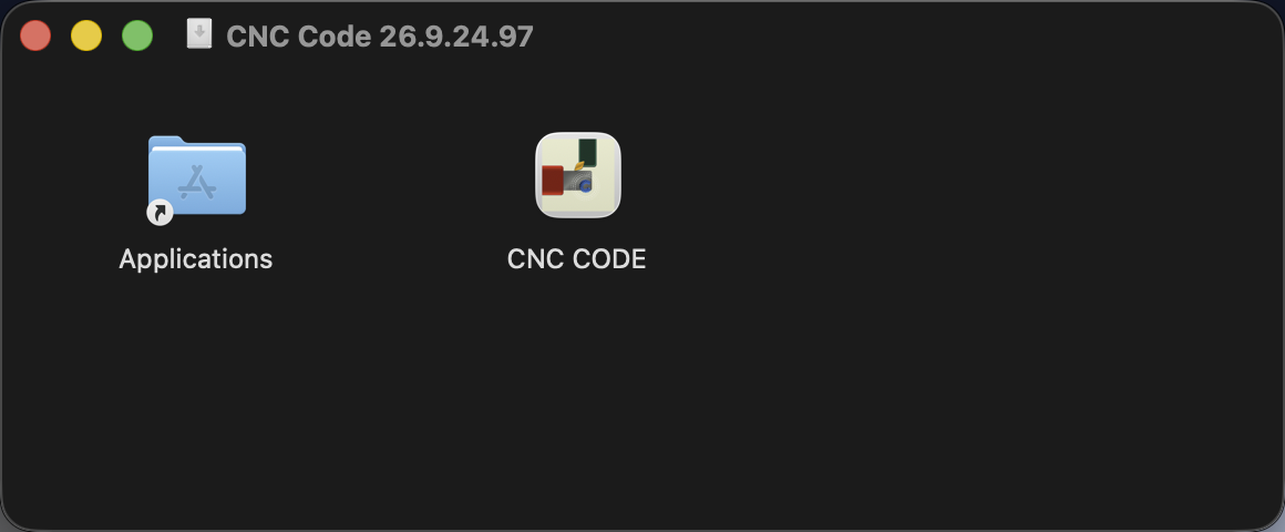
Drag the CNC CODE icon onto the Applications folder (the little arrow on the folder icon reminds you to do this), and the app is installed. From that point on, you'll find it just like any other app, in Launchpad or in the Applications folder.
1.2 Installation on Windows
On the product page on the website, click "Download Windows" to download the .exe installer.
Windows's Notice — and Why You Can Trust It
The first time you run the installer, Windows displays this notice:
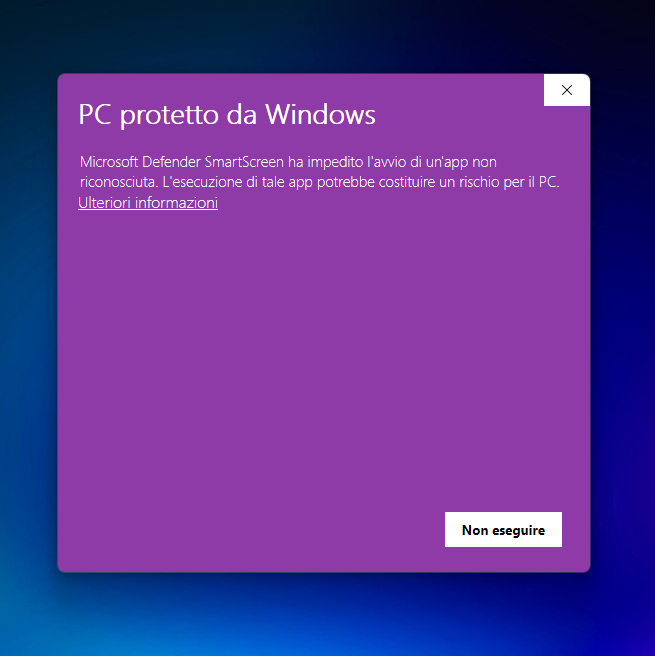
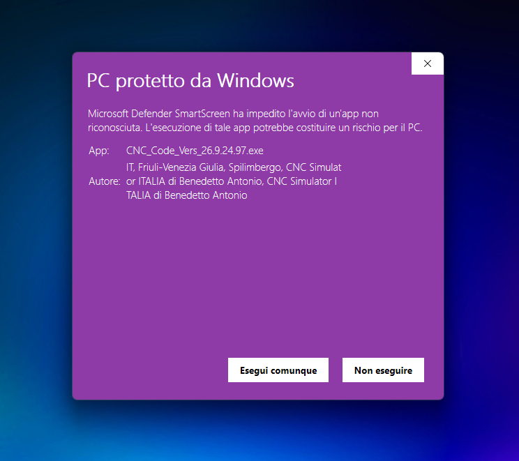
This is neither an error nor a problem with our software: SmartScreen displays this notice for any new app that has not yet built up a "reputation" with Microsoft, even if it is properly signed—this is normal in the early days after a certificate is activated. The question is, what happens if you click "Learn more":
The Wizard
From here on, it's a standard Windows installation: language, license agreement, installation folder, a desktop icon (if desired), and so on.
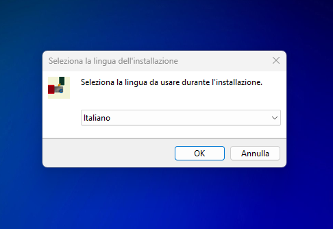
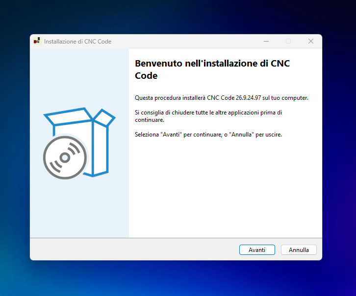
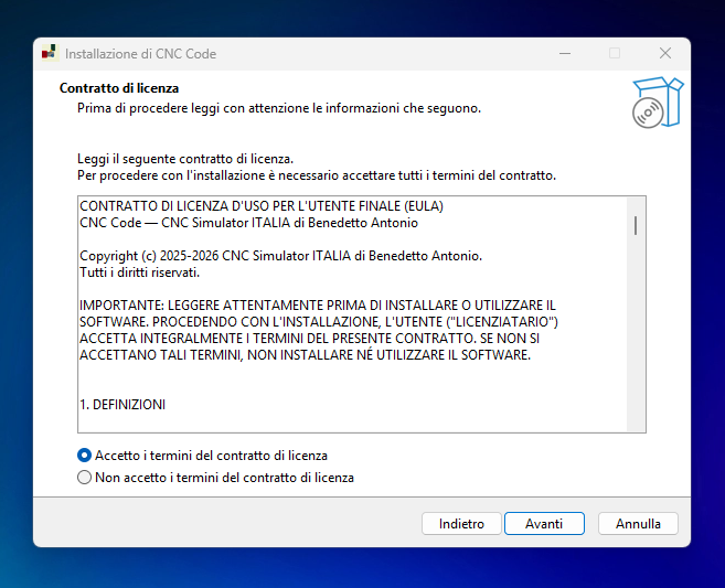
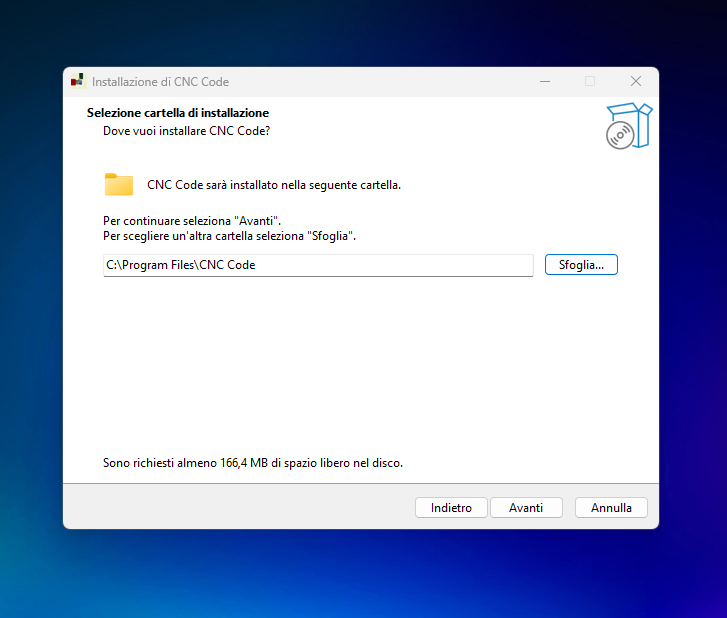
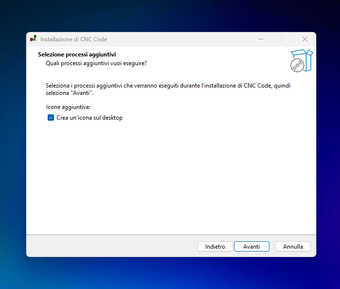
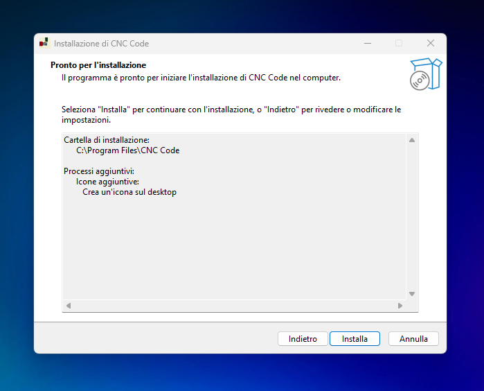
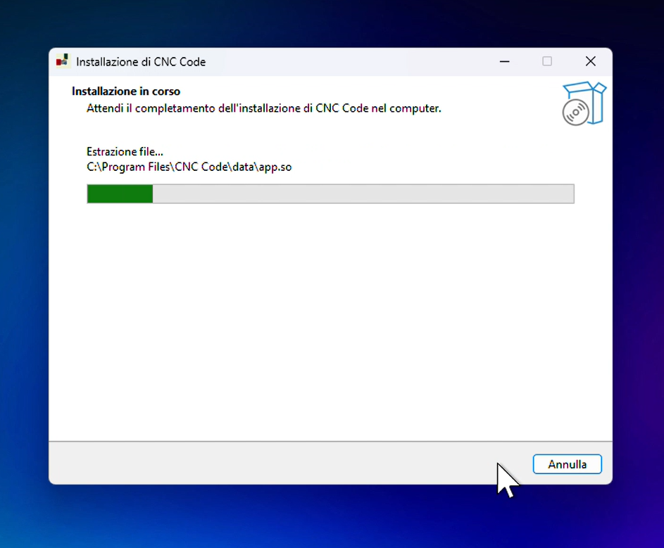
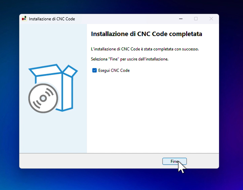
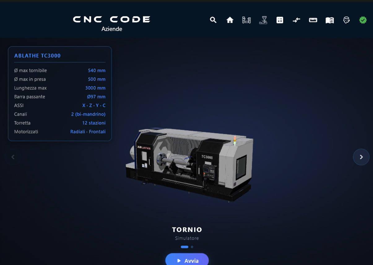
At the end, with Run CNC Code checked, by pressing End The app opens right away:
1.3 Digital Signature — on both platforms
One detail worth noting: CNC Code Desktop is digitally signed on both macOS and Windows, with a genuine certificate issued to CNC Simulator ITALIA—it is not an anonymous executable file downloaded from the internet.
| System | What Happens in Practice |
|---|---|
| macOS | The app is signed with an Apple Developer ID certificate and notarized by Apple — Gatekeeper does not display any notices. |
| Windows | The installer is signed with a code-signing certificate. At first, SmartScreen may still display the notice "PC protected by Windows" (this happens with any new app, regardless of the signature)—but when you expand it, it shows our actual name as the author, not “unknown publisher”: proof that the file is authentic. |
The Main Screen
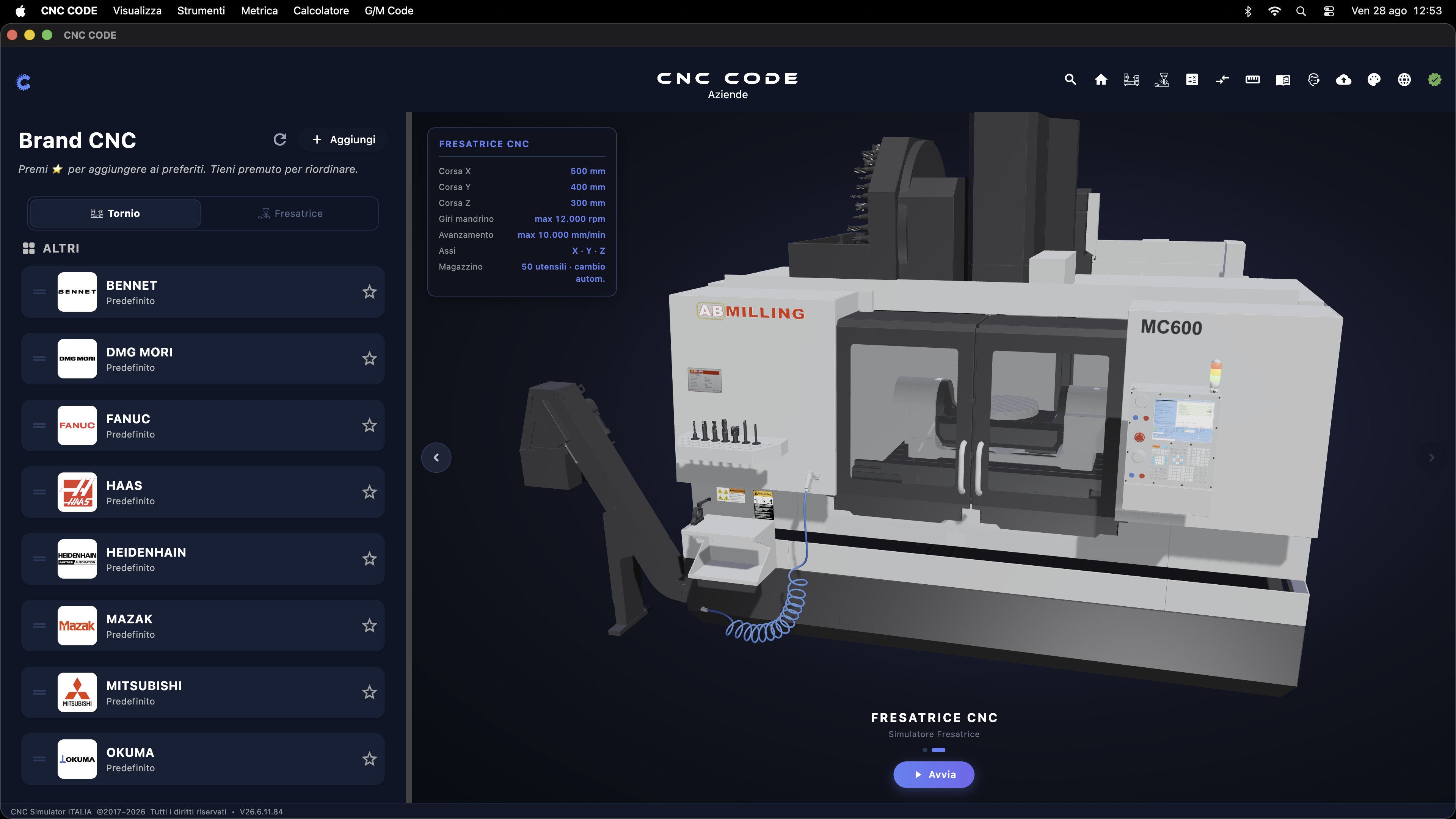
When you launch CNC Code on your desktop, the first thing you see is the main screen. This is the starting point for the entire application: from here, you choose the CNC brand, select the module (Lathe or Milling Machine), and access all the app's features.
2.1 General Overview
The screen is divided into three main areas that work together:
| Area | Location | Function |
|---|---|---|
| Left panel | Left Column | List of Available CNC Brands |
| Central Area | Main Area | Presentation and Launch of the Selected Simulator |
| Top Bar (Header) | At the top of the window | Logo, license profile, and quick access to features |
At the bottom of the window, you'll find the copyright bar with the version number of the installed software
(e.g., V30.6.11.84).
2.2 Left Panel — Brand CNC
The panel on the left is your brand selector and CNC control panel. At the top, you'll find two tabs that filter the list by machine type:
| Tab | Contents |
|---|---|
| LATHE | Brands and controls for CNC lathes |
| MILLING MACHINE | Brands and controls for CNC milling machines |
The available brands (under the "OTHERS" section) are: BENNET, DMG MORI, FANUC, HAAS, HEIDENHAIN, MAZAK, MITSUBISHI, OKUMA.
Favorites ☆
To the right of each brand, you'll see a small star. Tap it to add the brand to your favorites: The brand will move to the top of the list for quicker access in future sessions. Press and hold a favorite to reorder it.
Buttons at the top of the panel
2.3 Central Area — The Vehicle Fleet
The central area isn't the simulator itself, but the machine park carousel: a scrolling selection of the machine tools available in the app. Swipe left or right using the side arrows to browse the machines, choose the one you need, and press Start to enter it.
Technical Specifications Sheet
Each machine in the carousel displays a card in the upper-left corner listing its main technical specifications. Example for the CNC milling machine:
| Parameter | Value (example: Milling Machine) |
|---|---|
| Race X | 500 mm |
| Y-Axis Travel | 400 mm |
| Z Race | 300 mm |
| Spindle speed | max 12,000 rpm |
| Feed | max 10,000 mm/min |
| Axes | X · Y · Z |
| Tool magazine | 50 tools, automatic changeover |
Carousel Navigation ‹ ›
The side arrows (‹ on the left, › on the right)
scroll through the carousel of available machines: Lathe, Milling Machine, and future machines
that will be added with updates.
Start Button
Once you've found the machine you need, press the green ▶ Start button at the bottom: the app will load the selected machine with the CNC brand you chose in the left panel and take you directly into the simulation.
2.4 Top Bar (Header)
At the top center of the window, you'll see the CNC CODE logo, with the badge for the active license profile (e.g., Business, Personal, School) below it.
To the right of the logo is a row of 13 icons that provide quick access to the main sections of the app. We'll take a closer look at them in Chapter 3.
2.5 System Menu macOS
In the menu bar of macOS (at the top of the screen), you'll find the following options:
| Entry | Contents |
|---|---|
| View | Interface Display Options |
| Tools | Quick access to tools (calculator, conversions, etc.) |
| Metric | Metric Tables and Technical References |
| Calculator | Built-in calculator |
| G/M Code | Quick Reference for G and M Codes |
The Top Bar
The app's top bar is always visible at the top of the main screen. It contains 13 icons that provide direct access to the main features without having to navigate through menus. When you hover over each icon, a tooltip appears with the name of the feature.

3.1 Icon Overview
| # | Icon | Name | Function |
|---|---|---|---|
| 1 | 🔍 | Search | Opens the global search in the app |
| 2 | 🏠 | Home | Back to the main screen |
| 3 | ⚙️ | ABL Lathe | Quick Access to the Lath Simulator |
| 4 | ⚙️ | ABM Milling Machine | Quick Access to the Milling Machine Simulator |
| 5 | 🔢 | Parameters | Cutting Parameter Calculator |
| 6 | ↔️ | Converter | Unit Converter |
| 7 | 📏 | Metric | ISO Metric System Tables |
| 8 | 📖 | Manual | App User Manual |
| 9 | 👤 | Support | Contact and Technical Support |
| 10 | ☁️ | Backup | Data Backup and Recovery |
| 11 | 🎨 | Topic | Change Theme (Dark / Light) |
| 12 | 🌐 | Language | App Language Selection |
| 13 | ✅ | Account | Account and License Management |
3.2 Research
The magnifying glass opens the global search panel: a dark overlay that appears on top of the app without interrupting what you're doing. You can search from any screen—no need to go back to the home screen.
Initial State
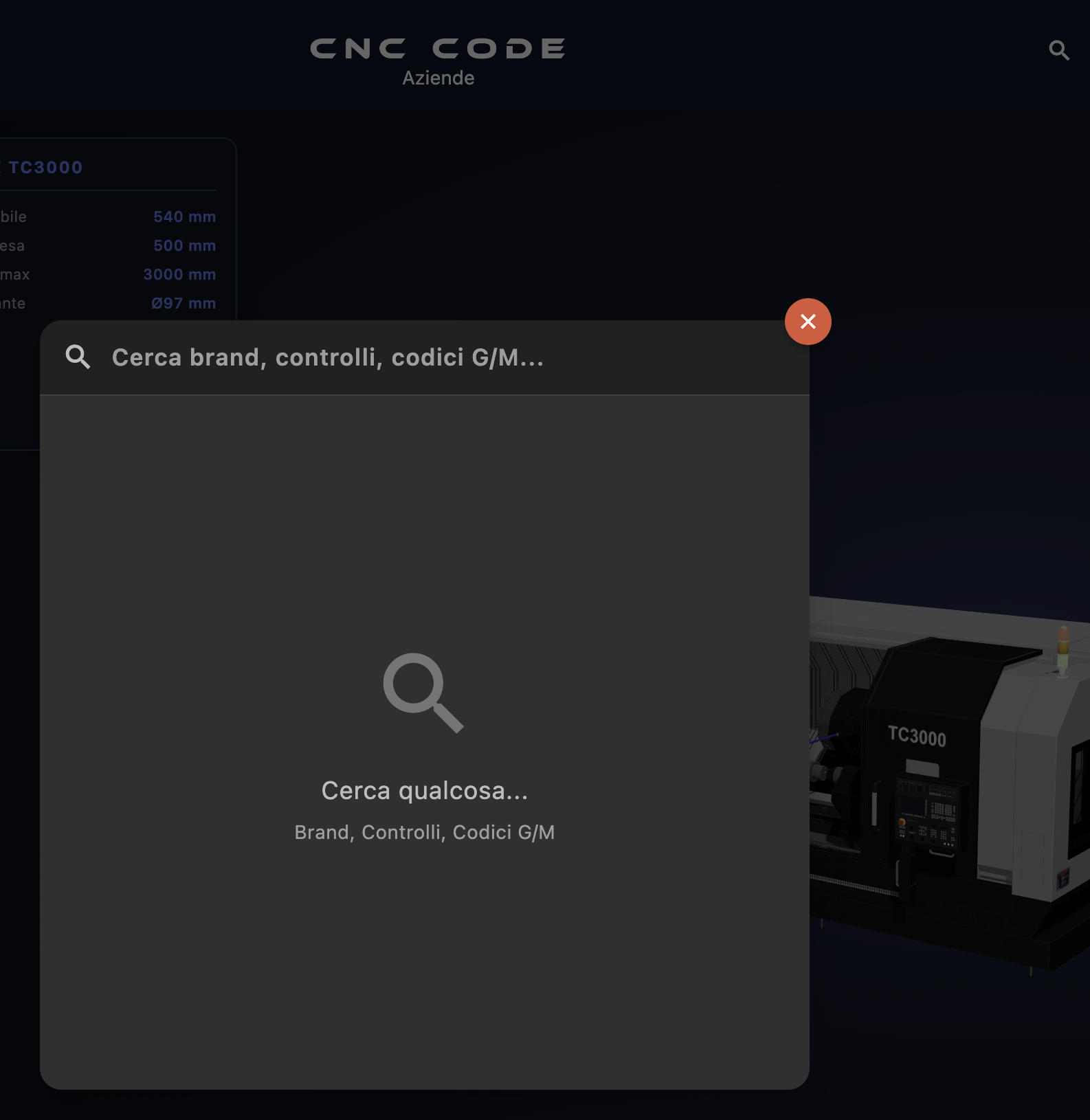
When first opened, the panel displays a text field with the placeholder "Search brands, controls, G/M codes..." and, in the center, the text "Search for something... Brands, Controls, G/M Codes," which indicates the three categories the search engine covers.
The red ✕ button in the upper-right corner closes the panel and returns you to the previous screen.
Real-Time Search
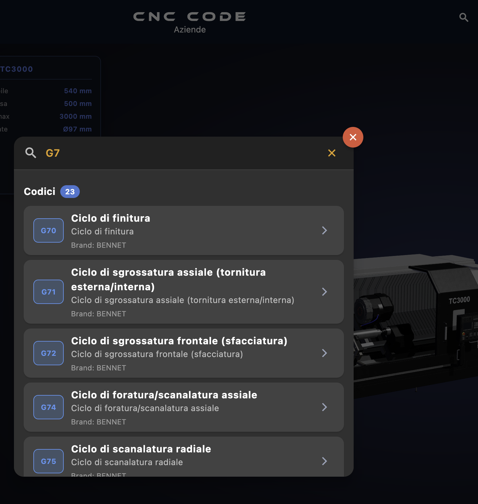
As soon as you start typing, the results appear instantly
without pressing Enter. In the example, when you type "G7," the app returns
23 codes that contain that string, grouped under the
"Codes" category.
How to Interpret the Results
Each result in the list shows:
| Element | Description |
|---|---|
| Blue badge | The G or M code (e.g., G70, G71...) |
| Title in bold | The name of the function (e.g., Finishing Cycle) |
| Gray text | Brief Description of the Feature |
| Brand | The CNC brand associated with that code (e.g., Brand: BENNET) |
| Arrow › | Tap to open the code's details page |
Search Categories
The search engine covers three areas at the same time:
Clear search and close
The yellow ✕ button that appears to the right of the text field deletes the entered text and clears the results, without closing the panel. The red ✕ button in the upper-right corner, on the other hand, closes the panel completely.
3.3 Home

The house icon always takes you back to the main screen, no matter which section you're in. It's the app's quick reset button.
3.4 ABL Lathe

Takes you directly to the lathe machine with the selected brand. We'll cover this in detail in the section dedicated to the lathe simulator.
3.5 Milling Machine ABM

Takes you directly to the milling machine with the selected brand. We'll cover this in detail in the section dedicated to the milling machine simulator.
3.6 Parameters
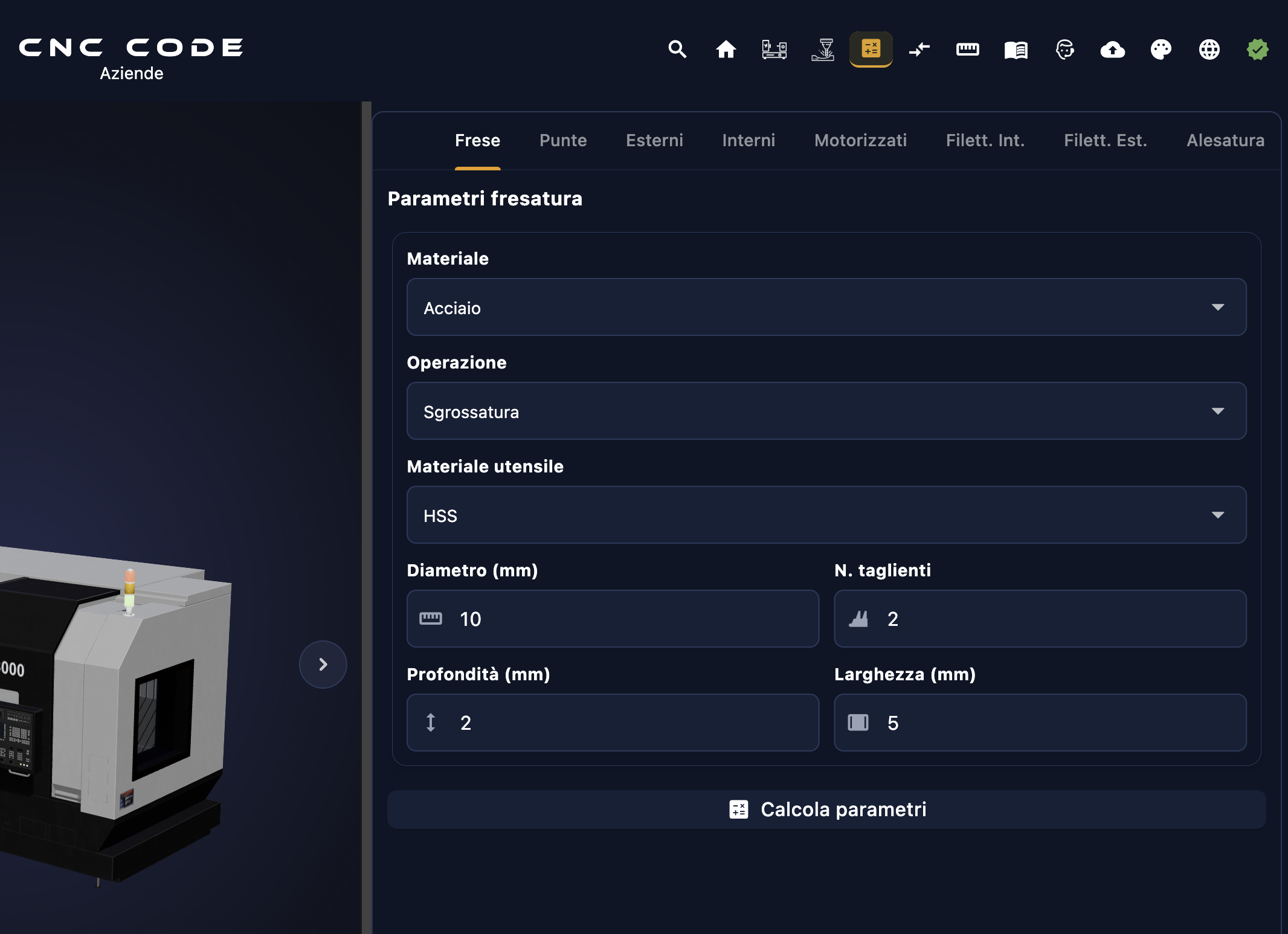
The "Parameters" section is the cutting calculator built into the app. Enter your machining operations data, and the app automatically calculates all the parameters needed to program the CNC machine: cutting speed, spindle speed, feed per tooth, and total feed. No manual calculations, no errors.
Available Machining Operations (tab)
At the top of the section, you'll find 8 tabs, one for each tool or machining operation category:
| Tab | Machining |
|---|---|
| Milling Cutters | Milling with end mills, face mills, and disc cutters |
| Tips | Drilling with twist drills |
| Exteriors | External turning (roughing, finishing, facing) |
| Interior | Internal Turning (Boring, Tool Boring) |
| Motorized | Powered Tools on a Lathe (Live Tooling) |
| Internal Threads | Internal Threading (taps, G84/G76 cycles) |
| External Threads | External Threading (taps, G76/G92 cycles) |
| Boring | Precision Boring with Reamers |
Input fields — what to enter
For each tab, the app requests a set of values. Example for the "Milling Cutters" tab:
| Field | What to Include | Why It's Needed |
|---|---|---|
| Material | The material of the workpiece (steel, aluminum, cast iron, stainless steel, titanium...) | Determine the recommended cutting speed Vc [m/min] — each material has its own cutting resistance |
| Operation | Type of pass: Roughing or Finishing | Roughing uses a lower Vc and higher feed rates; finishing uses a higher Vc and lower feed rates for better surface quality |
| Tool Material | HSS, Hard Metal (HM/Carbide), Ceramic, CBN... | Carbide tools can handle much higher Vc values than HSS — the calculation changes accordingly |
| Diameter (mm) | The diameter of the milling cutter or drill bit in millimeters | Key to calculating n: for a given Vc, a smaller tool must rotate faster |
| No. of cutting edges | The number of cutting edges (teeth) on the tool | More teeth → greater total feed rate for the same feed rate per tooth |
| Depth (mm) | Axial depth (ap) in millimeters | It affects the shear stress and the selection of the recommended feed per tooth |
| Width (mm) | Radial stroke width (ae) in millimeters | Determines the radial load on the milling cutter — affects the power required and the sustainable feed rate |
The formulas used by the calculator
Once you tap "Calculate Parameters," the app applies the standard formulas used in mechanical engineering. You don't need to memorize them—the app takes care of that—but it's helpful to understand what's behind them:
| Calculated metric | Formula | Units |
|---|---|---|
| Spindle speed (n) | n = (Vc × 1000) / (π × D) |
revolutions per minute — RPM |
| Feed per tooth (fz) | From internal tables based on material, tool, and operation type | mm/tooth |
| Table Feed Rate (Vf) | Vf = fz × z × n |
mm/min → F value in the CNC program |
| Cutting Speed (Vc) | From internal material/tool tables — starting point for the calculation | m/min |
Key to symbols:
| Symbol | Meaning |
|---|---|
Vc | Cutting speed [m/min] — depends on the workpiece material and the tool material |
D | Tool Diameter [mm] |
π | Pi ≈ 3.14159 |
fz | Feed per tooth [mm/tooth] |
z | Number of cutting edges (teeth) on the tool |
n | Spindle Speed [RPM] |
Vf | Table feed rate [mm/min] — the F value to be entered into the CNC program |
3.7 Converter
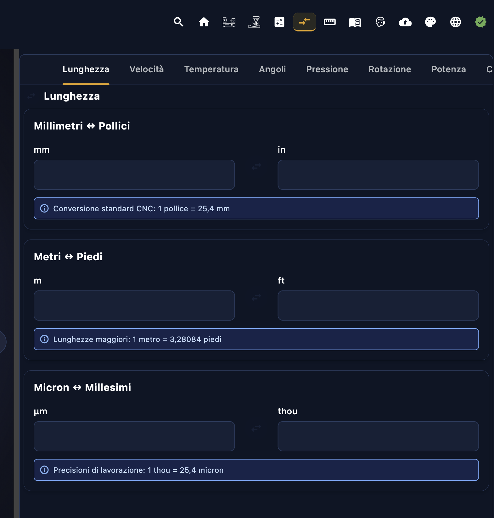
The Converter is a tool for quickly converting between units of measurement in the metric system (ISO) and the imperial system (inches), which is essential when working with American drawings, imported tools, or machines with inch-based controls. All conversions are bidirectional: you can enter a value in either field, and the result appears instantly in the other.
Available Categories (tab)
The converter is organized into tabs by physical quantity:
| Tab | Magnitude | Typical Use in CNC |
|---|---|---|
| Length | Linear Measurements | Workpiece dimensions, tool travels, offsets |
| Speed | Feed and Cutting Speeds | Convert F [mm/min] ↔ [in/min], Vc [m/min] ↔ SFM |
| Temperature | Temperatures | Coolant Temperature, Material Specifications |
| Angles | Angular Measurements | Tool angles, inclinations, degrees ↔ radians |
| Pressure | Pressures | Coolant Pressure, Pneumatic Lock [bar ↔ PSI] |
| Rotation | Rotational speed | Spindle speed [RPM] ↔ rad/s |
| Power | Machine Power | Spindle power [kW ↔ HP] |
Length Tab — Details
The most frequently used tab in the workshop. It contains three stacked converters, each with a contextual note reminding users of the reference convention:
| Conversion | Units | App Note | When to use |
|---|---|---|---|
| Millimeters ↔ Inches | mm ↔ in | "Standard CNC conversion: 1 inch = 25.4 mm" | Dimensions on American drawings, tools in inches (e.g., Weldon end mills), G20/G21 settings |
| Meters ↔ Feet | m ↔ ft | "Longer lengths: 1 meter = 3.28084 feet" | Machine travels, bar lengths, Anglo-Saxon technical documentation |
| Microns ↔ Thousandths | μm ↔ thou | "Machining tolerances: 1 thou = 25.4 microns" | Precision tolerances, roughness, and mating clearances with specifications in thousandths |
How Bidirectional Conversion Works
Each converter has two fields connected by an arrow ↔. Enter the value in any of the two fields—the result appears automatically in the other without pressing any keys. You can start from either unit.
3.8 Metric
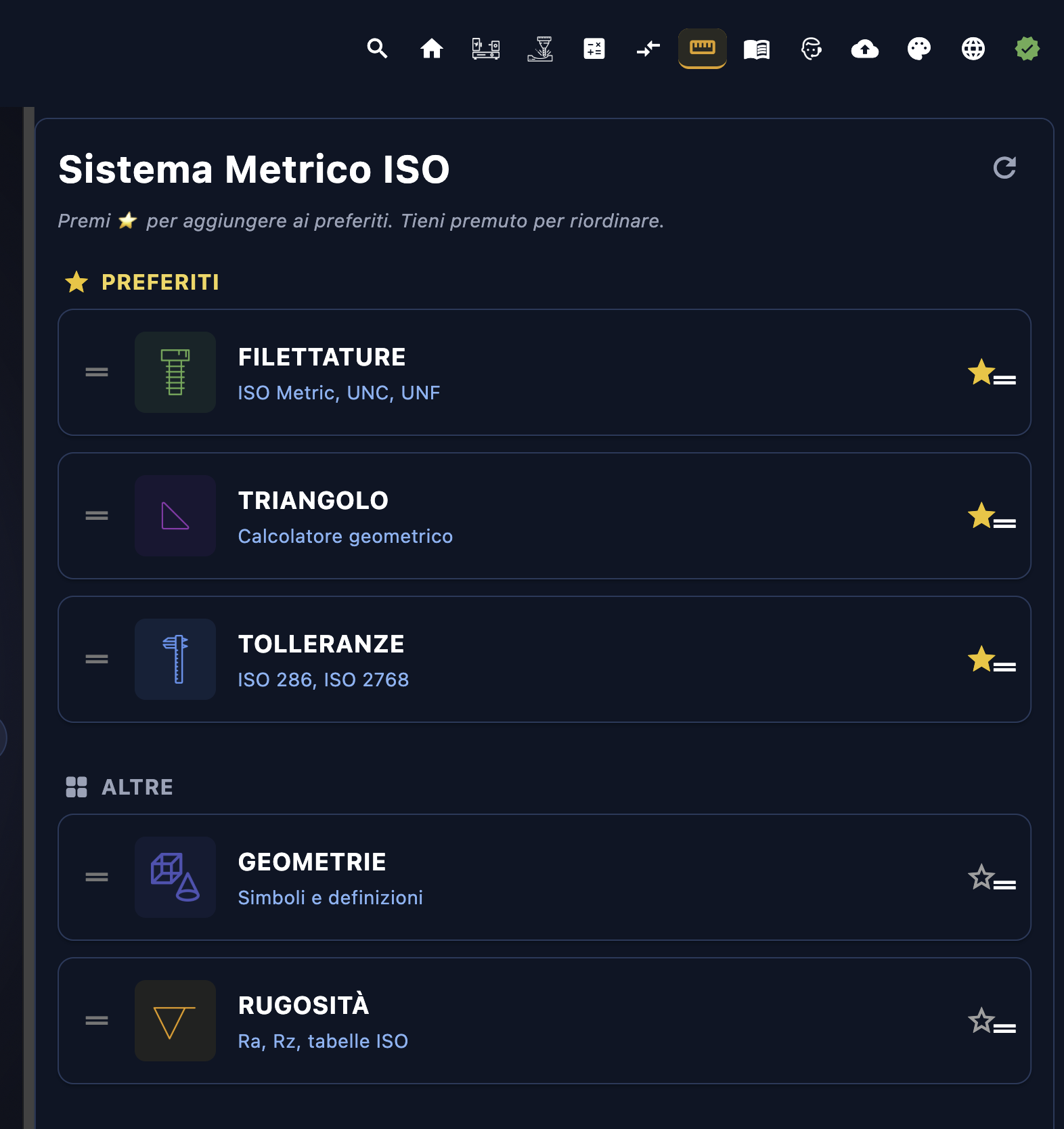
The Metrics section is the technical reference guide built into the app: it brings together in one place all the ISO standards commonly used in the workshop— threads, tolerances, geometries, surface roughness, and geometric triangle calculations. No more flipping through paper tables.
Favorites System
At the top of the screen, you'll find the section FAVORITES (⭐) with the entries you use most often. To add an entry to your favorites, tap the star ☆ next to the name—it turns into ⭐ and moves to the top of the list. To change the order, press and hold and drag. The button ↺ The button in the upper-right corner restores the default order.
The 5 available sections
| Section | Contents | Standard |
|---|---|---|
| Threads | Metric and Imperial Thread Charts | ISO Metric, UNC, UNF |
| Triangle | Triangle Geometry Calculator | Applied Trigonometry |
| Tolerances | Calculation of Dimensional Deviations | ISO 286, ISO 2768 |
| Geometries | Symbols and Definitions of Geometric Tolerances | ISO 1101 |
| Roughness | Ra, Rz, and Finishing Reference Tables | ISO 4287 |
Threads
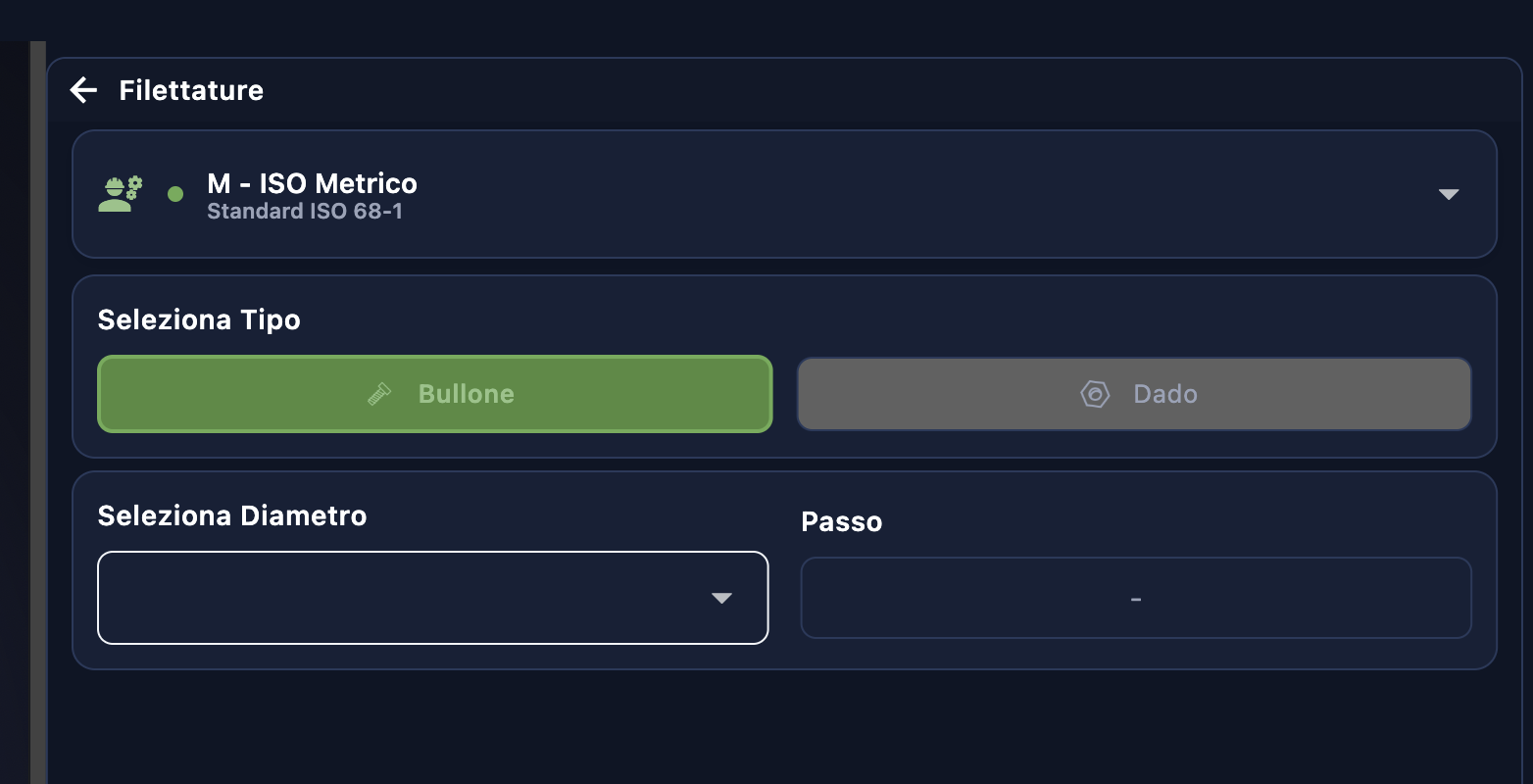
Select the standard, type, and diameter to determine the pitch and all thread specifications:
| Field | Options | Description |
|---|---|---|
| Standard | M – ISO Metric, UNC, UNF |
M ISO Metric (ISO 68-1):
European standard metric threads (M3, M6, M10...) UNC – Unified National Coarse: coarse pitch, U .S. imperial system UNF – Unified National Fine: fine pitch, U.S. imperial system |
| Type | Bolt / Nut |
Bolt:
external thread (male) — screws, studs Nut: internal thread (female) — nuts, threaded holes |
| Diameter | Dropdown menu listing all diameters for the selected standard | Nominal diameter (e.g., M10 = Ø10 mm) |
| Step | Self-completed | Distance (mm) between two consecutive threads — updates automatically when the diameter changes |
Triangle Calculator
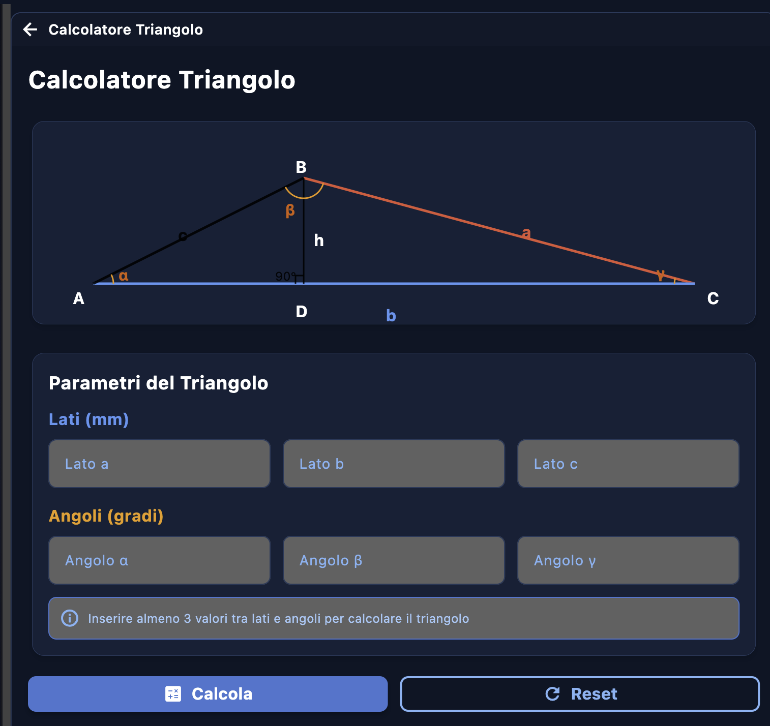
Solves any general triangle using at least 3 known values among the sides and angles—any combination works. The diagram shows vertices A, B, C, sides a, b, c, and height h.
| Group | Field | Units |
|---|---|---|
| Sides | Side a — opposite vertex A | mm |
| Side b — opposite vertex B (base) | mm | |
| Side c — opposite vertex C | mm | |
| Angles | Angle α — in A | degrees ° |
| Angle β — in B | degrees ° | |
| Angle γ — in C | degrees ° |
Click "Calculate" to find all the missing values (law of sines and law of cosines). "Reset" clears everything.
Tolerances
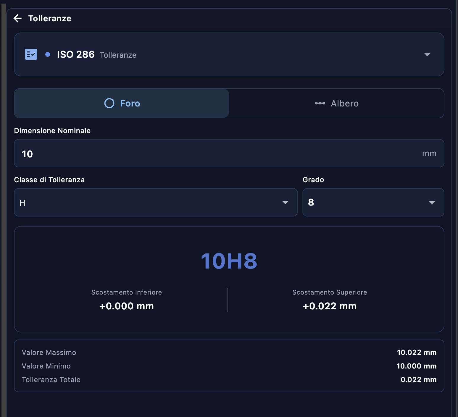
Calculate dimensional deviations according to ISO 286 (shaft-to-hole fittings) and ISO 2768 (general tolerances).
| Field | Options | Description |
|---|---|---|
| Type | Hole / Shaft |
Hole:
tolerance on the female part (uppercase letters: H, G, F...) Shaft: tolerance on the male part (lowercase letters: h, g, f...) |
| Nominal Size | Value in mm | Nominal diameter of the hole or shaft |
| Tolerance Class | ISO Letter | Position of the tolerance zone relative to the nominal dimension (H = bottom of hole, lower deviation = 0) |
| Grado | IT1 → IT16 | Tolerance grade: Low IT = tight tolerance (high precision), High IT = wide tolerance |
Calculated results (example: 10H8):
| Result | Example value | Meaning |
|---|---|---|
| Lower Deviation (EI) | +0.000 mm | Minimum permissible deviation from the nominal dimension |
| Upper Deviation (ES) | +0.022 mm | Maximum permissible deviation from the nominal value of the dimension |
| Maximum Value | 10,022 mm | Maximum acceptable size |
| Minimum Value | 10,000 mm | Minimum Acceptable Size |
| Total Tolerance | 0.022 mm | Tolerance Range (ES − EI) |
ISO Geometries
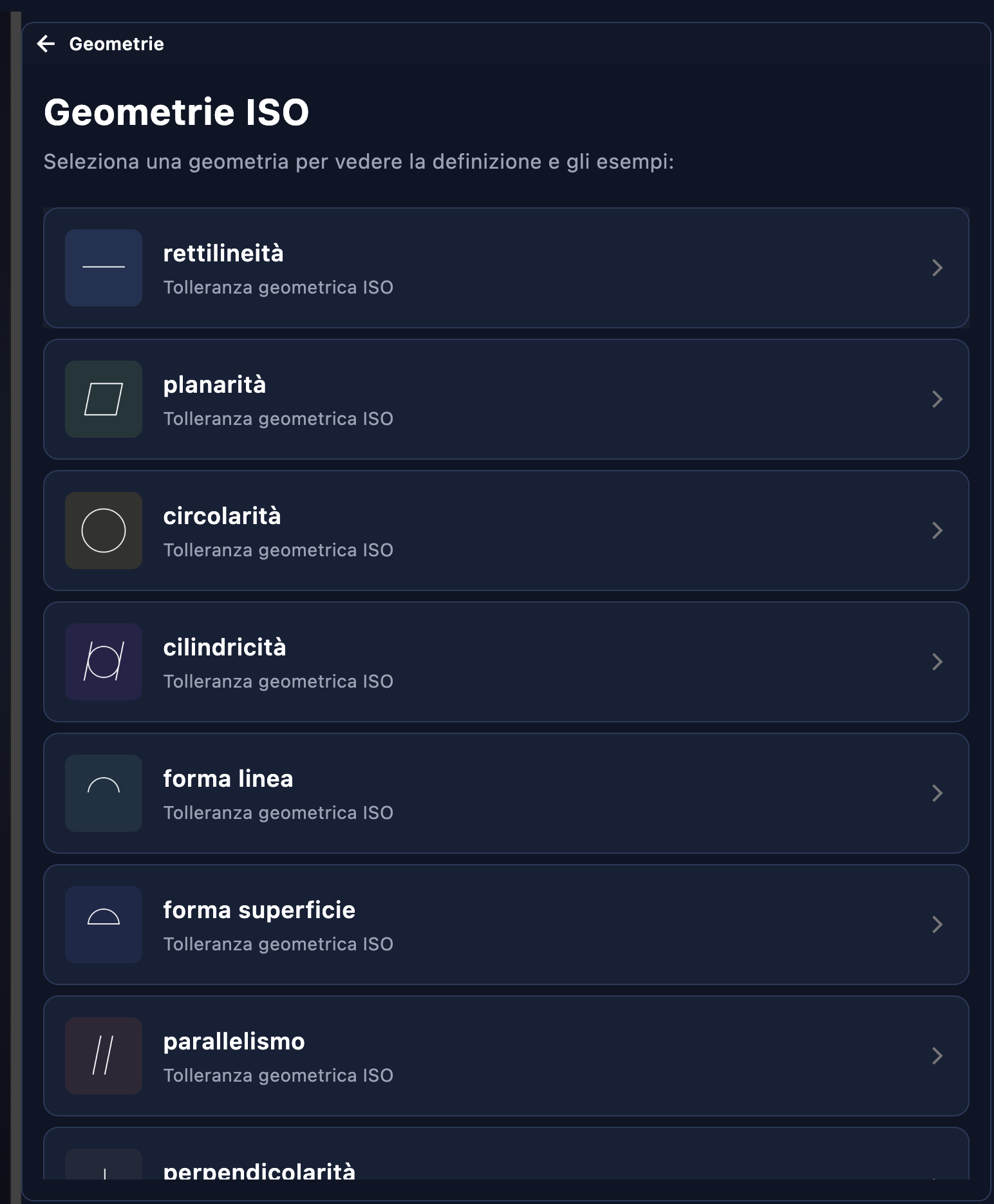
Visual Dictionary of Geometric Tolerances According to ISO 1101. Select an entry from the list to view its definition, GD&T symbol, and application examples.
| Symbol | Tolerance | Category | What it checks |
|---|---|---|---|
| Dimensional Tolerances | |||
⏤ | Straightness | Shape | The degree to which a linear element deviates from an ideal straight line. Applicable to edges, axes, and generatrices of cylinders. |
⏥ | Flatness | Shape | The degree to which a surface deviates from an ideal plane. Essential for reference surfaces and fit planes. |
○ | Circularity | Shape | The extent to which a circular cross-section deviates from a perfect circle. It is measured cross-section by cross-section, not over the entire cylinder. |
⌭ | Cylindricity | Shape | Combined straightness and circularity deviation over the entire cylindrical surface. The most stringent tolerance for precision shafts. |
⌒ | Shape Line | Shape | Tolerance on 2D profiles of any shape (e.g., curved profiles, complex fillets). Requires a reference datum. |
⌓ | Surface Shape | Shape | Tolerance on 3D surfaces of any shape. Used for sculpted surfaces and CAM profiles. |
| Alignment Tolerances | |||
∥ | Parallelism | Guidance | The degree to which an element is parallel to a datum. Applicable to planes, axes, and lines relative to a reference plane or axis. |
⊥ | Perpendicularity | Guidance | The degree to which an element is perpendicular to a datum. Used for turning shoulders, orthogonal holes, and reference pins. |
∠ | Angularity | Guidance | The degree to which an element conforms to a theoretical angle relative to a datum. For inclined surfaces, dovetails, and angled planes. |
| Positional Tolerances | |||
⊕ | Location | Location | The deviation of the actual position of an element (hole, edge, axis) from its theoretically exact position. This is the most commonly used method for hole patterns. |
◎ | Concentricity / Coaxiality | Location | The extent to which the axis of an element coincides with the axis of a datum. Concentricity for 2D sections, coaxiality for 3D axes. Typical for rotating shafts. |
⊜ | Symmetry | Location | The degree to which an element is symmetrical with respect to a median reference plane. For grooves, tabs, and symmetrical profiles. |
| Runout Tolerances | |||
↗ | Circular runout | Runout | Radial or axial variation measured on a single section during a complete rotation around the datum axis. Indicates eccentricity and sectional waviness. |
⇗ | Total Runout | Runout | Similar to circular runout, but measured over the entire surface during rotation. It combines shape, position, and orientation into a single inspection. It is the most stringent of the runout tolerances. |
Surface Roughness
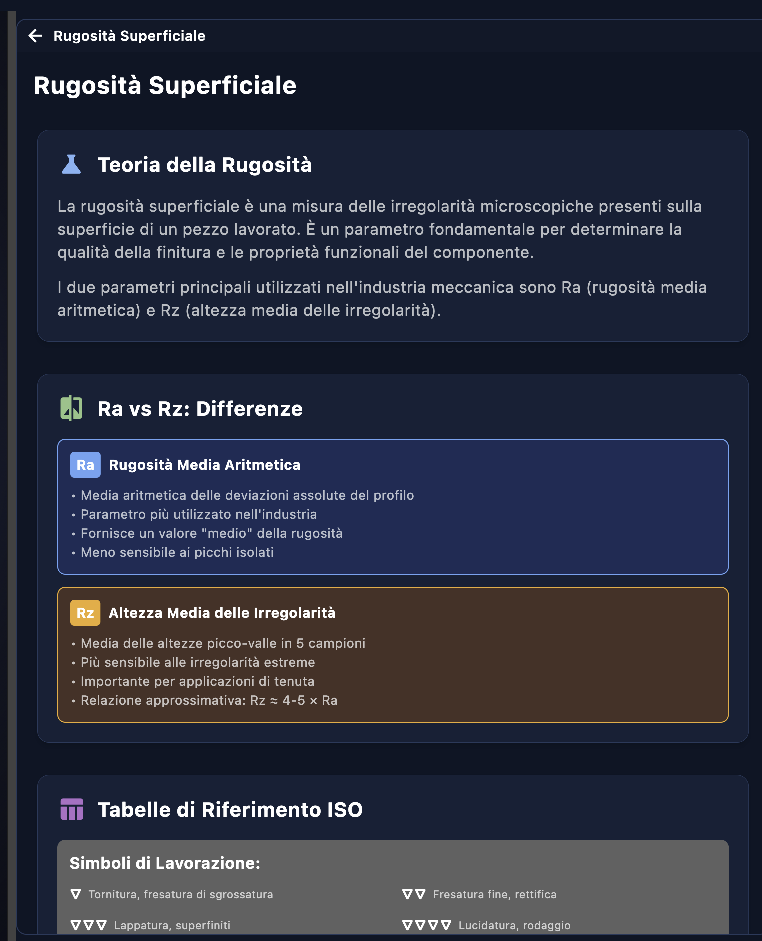
It explains surface finishing parameters and provides ISO tables to link the symbols on the drawing to the machining processes that produce them.
| Parameter | Name | What does it measure? |
|---|---|---|
| Ra | Arithmetic Mean Roughness | Arithmetic mean of the absolute deviations of the profile from the mean line. The most commonly used parameter in the industry—it provides an "average" value for roughness that is less sensitive to isolated peaks. |
| Rz | Average Height of Irregularities | Average of peak-to-valley heights across 5 contiguous samples. More sensitive to extreme irregularities. Essential for sealing applications (gaskets, O-rings). Report: Rz ≈ 4–5 × Ra |
Table of ISO Machining Symbols:
| Symbol | Traditional Machining Operations | Ra (indicative) |
|---|---|---|
| ▽ | Turning, roughing milling | Ra 6.3–25 μm |
| ▽▽ | Fine milling, grinding | Ra 1.6–6.3 μm |
| ▽▽▽ | Lapping, Superfinishing | Ra 0.4–1.6 μm |
| ▽▽▽▽ | Polishing, Breaking In | Ra < 0.4 μm |
3.9 Manual
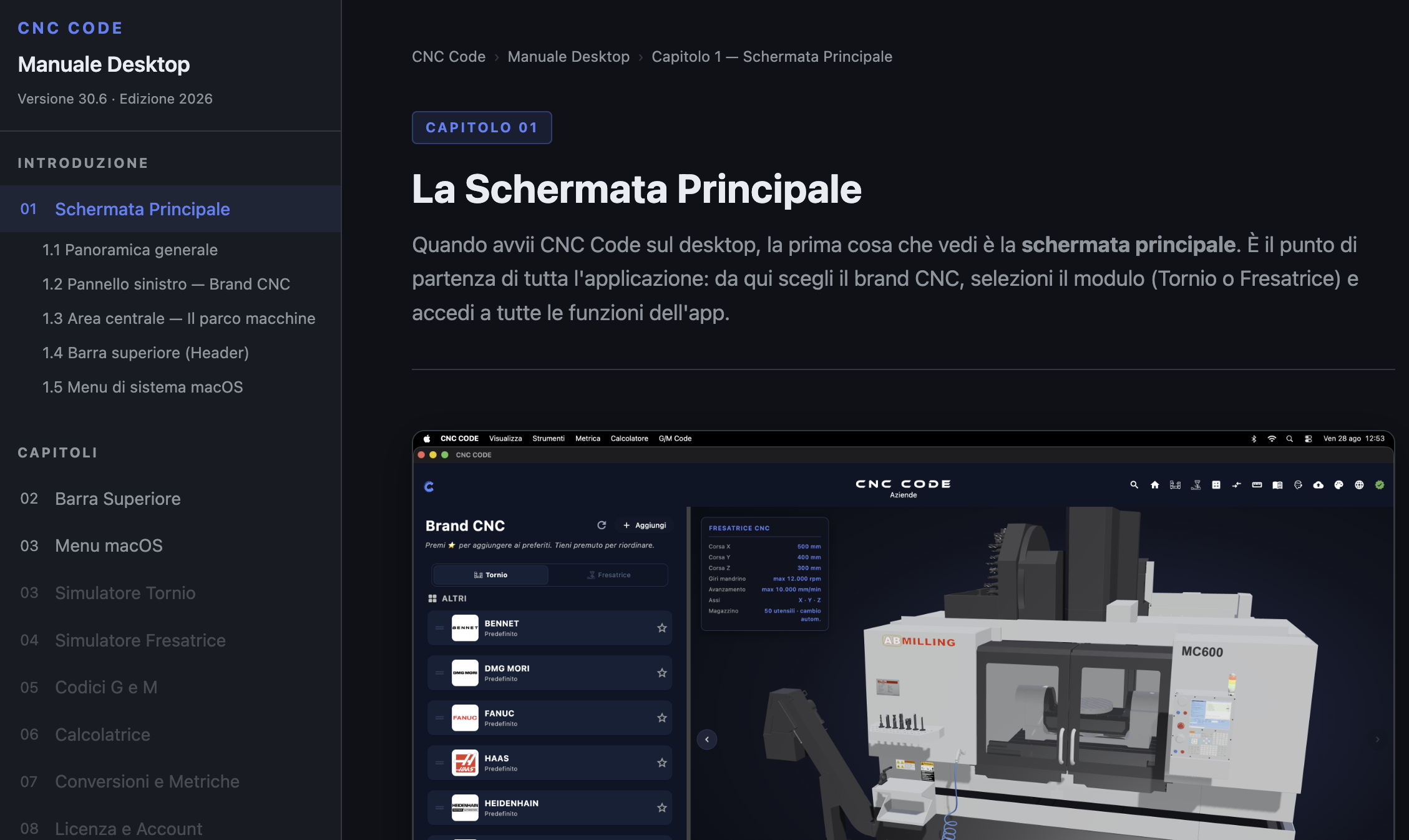
On a desktop, the Manual icon opens this manual directly in the system browser. You're already here—you're reading exactly what opens when you click that icon.
The manual is organized with a navigation sidebar on the left that tracks your reading progress in real time, along with numbered chapters and subsections for each feature of the app. It is continuously updated with each new version of CNC Code.
3.10 Support
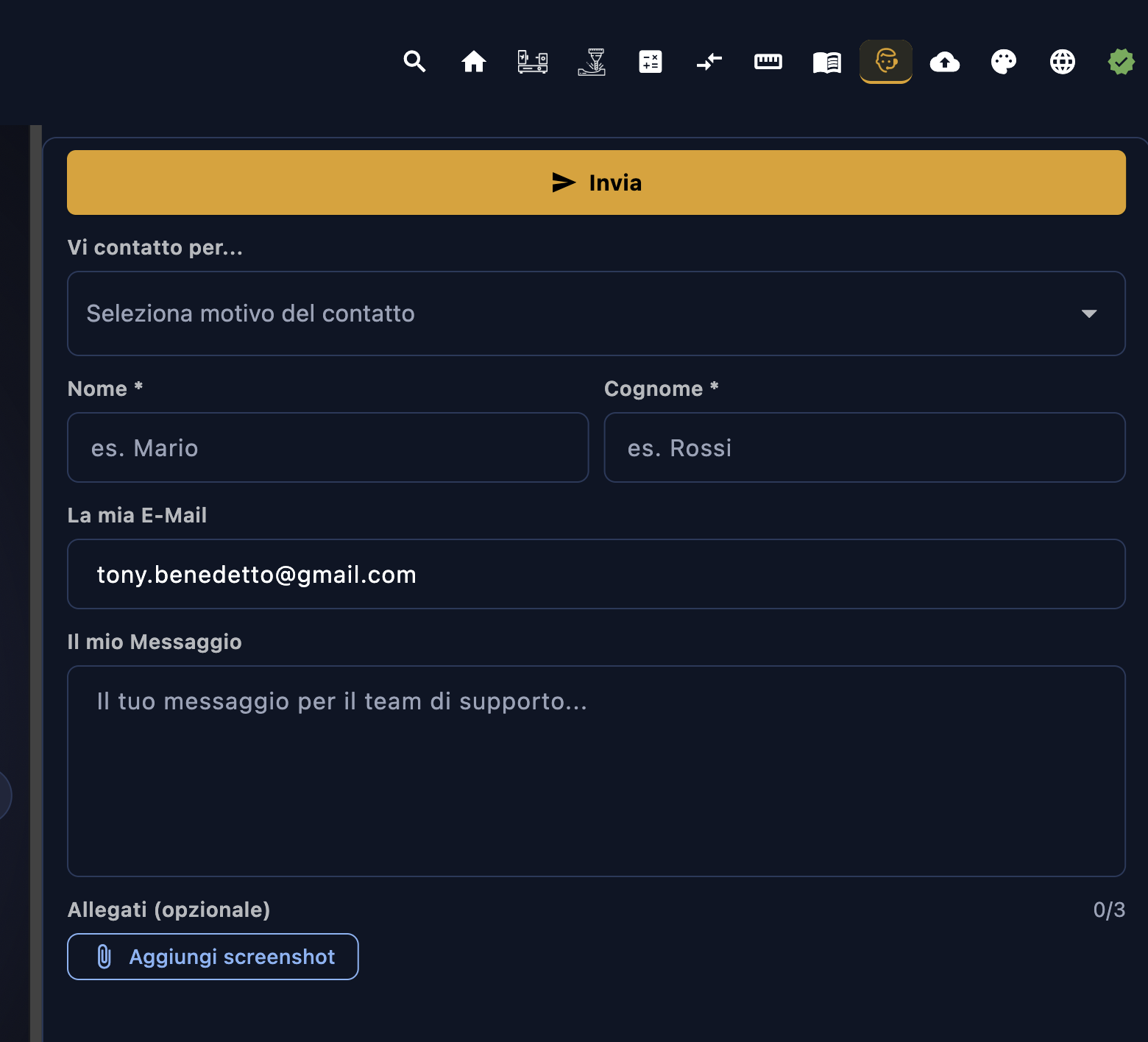
The Support section includes a contact form that connects you directly to the CNC Simulator Italia team. You can report bugs, request technical assistance, or send any questions without leaving the app.
Form Fields
| Field | Required | Description |
|---|---|---|
| I am contacting you to... | Yes | Dropdown menu to select the reason for contacting us (e.g., bug report, feature request, license support, sales information...) |
| Name | Yes * | Your name |
| Last Name | Yes * | Your last name |
| My Email | Yes | The email address to which the team will reply. It is automatically pre-filled with your CNC Code account email address. |
| My Message | Yes | The text of your message. The more details you provide (app version, operating system, steps to reproduce the issue), the faster you'll receive a response. |
| Attachments | No | You can attach up to 3 screenshots using the "Add Screenshot" button. This is useful for visually demonstrating a bug or unusual behavior. |
Send
Click the orange ▶ Send button at the top of the form to send the message. You will receive a reply via email at the address provided in the Email field—usually within 24 to 48 hours on business days.
How to Contact Us
In addition to the form built into the app, you can reach us through these channels:
| Channel | When to Use It |
|---|---|
| Forms in the app (this section) | For any inquiries—bugs, technical questions, requests for custom checks. This is the preferred channel because it automatically includes your account information. |
| cncsimulator.it | For sales information, school license purchases, corporate quotes, and documentation for customs inspections. |
| Direct Email | If the form is unavailable for any reason, please write to us at the address listed on the website. Be sure to include the app version and operating system. |
3.11 Backup
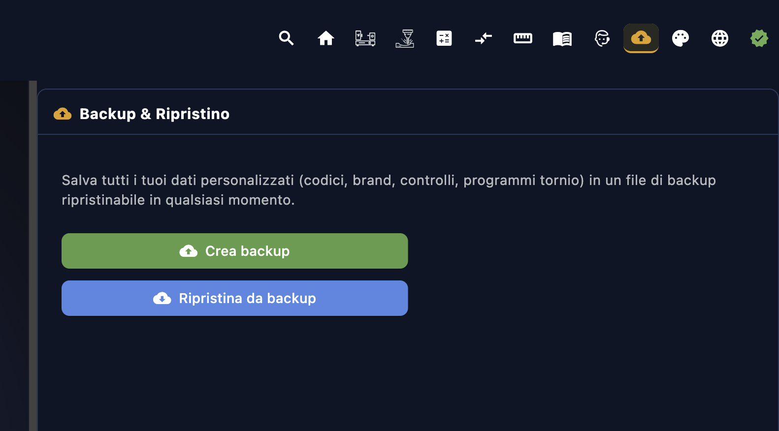
The Backup & Restore section lets you save all the customization work you've accumulated over time into a single file and restore it at any time, even on another device or after a reinstallation.
What Is Saved
The backup includes all of the app's user-specific data:
- Custom G/M codes — all codes added or modified from the default
- Brands and Custom Controls — CNC controls that have been purchased or manually configured
- Saved lathe programs — G-code programs saved in the lathe simulator
- Preferences — language, theme, layout, and other user settings
The app's default data (already present at installation) is not included because it is already built into the app itself and is not at risk of being lost.
Create a backup ☁
The green ☁ Create Backup button generates a file named .cnc that
contains all the data listed above. The system opens the operating system’s save panel
(Finder at macOS, File Explorer at Windows), where you can choose the name and location
of the file. Store this file in a safe place—iCloud folder, Google Drive, USB
flash drive—so you don’t lose it in the event of a disk failure.
Restore from backup ☁
The blue ☁ Restore from Backup button opens the operating system's file selection panel.
Select the previously saved .cnc file, and the app
will automatically import all the data it contains, overwriting the current data.
3.12 Topic
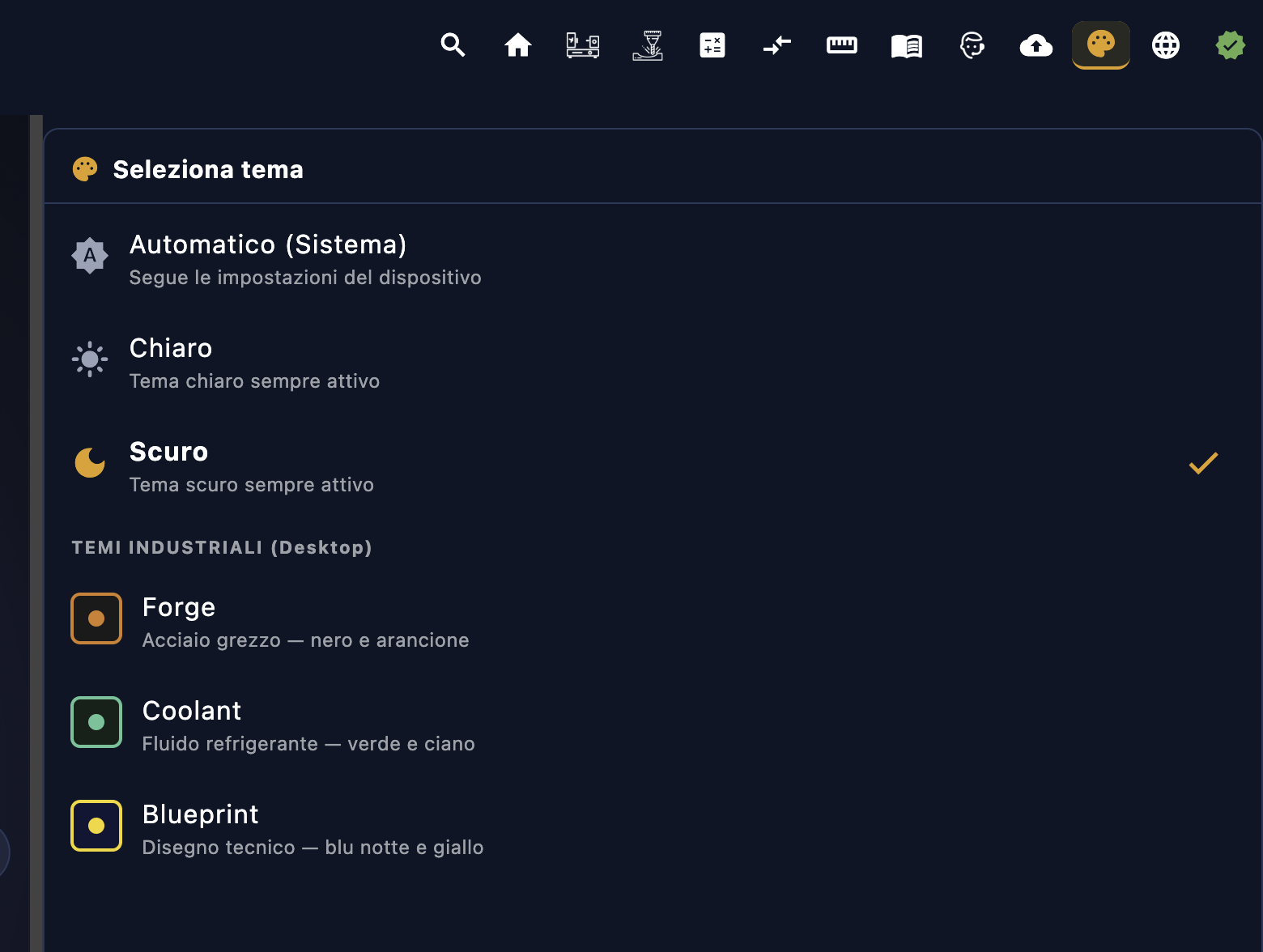
CNC Code It comes with the "dark" theme set as the default—designed for workshop environments where screens are used in varying lighting conditions, and the reduced contrast causes less eye strain during long shifts. There's no need to change it; it works great just the way it is.
However, if you prefer to use the light theme—perhaps on a bright monitor at the office or simply because you like it—the app offers this option. The available choices are:
- Dark — black/dark gray background, high-contrast text and icons (default)
- Light — white/light gray background, ideal for brightly lit environments
The selection is saved permanently and applied immediately without a restart. You can also change the theme from the "macOS" menu under View → Change Theme.
3.13 Language
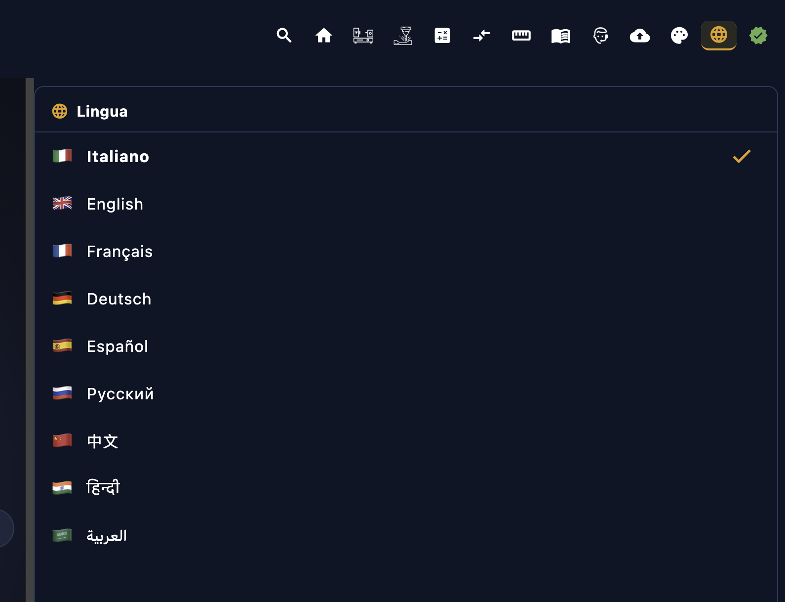
CNC Code It is available in 9 languages. From the Language panel, you can change the interface at any time without restarting the app—the change takes effect immediately and is saved permanently.
The supported languages are:
| Flag | Language | Spoken primarily in |
|---|---|---|
| 🇮🇹 | Italian | Italy, Switzerland |
| 🇬🇧 | English | The U.S., the U.K., Australia, Canada, and the international language of reference |
| 🇩🇪 | German | Germany, Austria, Switzerland — a very strong CNC market |
| 🇫🇷 | French | France, Belgium, Switzerland, North Africa |
| 🇪🇸 | Spanish | Spain, Latin America |
| 🇵🇹 | Portuguese | Portugal, Brazil |
| 🇵🇱 | Polish | Poland — one of Europe's leading manufacturers of machine tools |
| 🇷🇴 | Romanian | Romania |
| 🇹🇷 | Turkish | Turkey — Rapidly Growing Metalworking Industry |
3.14 Account
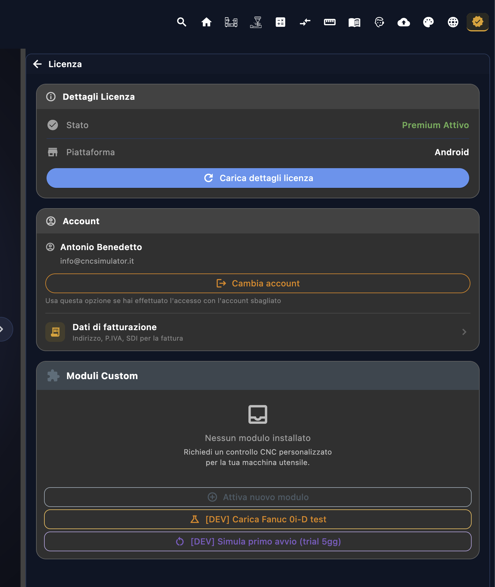
The Account section is the control center for your CNC Code license. From here, you can manage access, transfer the license to another device, and check what your plan includes.
Log In and Log Out
When you launch the app for the first time, it will ask you to sign in using the credentials you created at the time of purchase at cncsimulator.it. Once you've signed in, your session remains active permanently—you don't have to re-enter your password every time you open the app.
The Logout button logs the account out of the current device and deactivates the "Premium" license locally. Use it when you want to let someone else use the device or when you want to transfer the license to another computer.
Transferring a License Between Devices
The CNC Code license is tied to a specific user and can be active on only one device at a time. If you have a new computer or want to use the app on a different device, you can transfer it: log out of the current device, log in with the same credentials on the new device, and the license will transfer automatically.
Custom License Types and Controls
CNC Code It offers three license profiles, each designed for a specific category of users. The most significant difference concerns access to CustomControls —custom CNC controls tailored to specific machines (Mitsubishi , Mazak, Okuma , customized Siemens , etc.).
| Profile | Who is it for? | Custom Checks | Level of detail |
|---|---|---|---|
| Private | Operator, programmer, enthusiast — personal use | Up to 2 custom checks | Basic Version — Standard Cycles, Main Codes |
| Company | Workshops, production departments, design offices | Unlimited (upon submission of documentation) | Full version — custom cycles, advanced parameters, manufacturer-specific dialects |
| School | Technical schools, vocational training centers | Included in the training package | Adapted to the agreed-upon educational curriculum |
Private License — Your Personal Space
The Private license provides full access to the simulators (lathe and milling machine), all G/M codes for the included brands, and the calculation functions. In addition, you can purchase up to 2 basic “Custom” controls—useful if you’re working on a specific machine not covered by the standard brands and need a simulator that accurately replicates that control. The limit of 2 is intended for individual use: if you need more, the Company plan is the right choice.
Business License — Unlimited Professional Use
Companies can obtain complete and unlimited “Custom” tests, built with the highest level of detail: manufacturer-specific test cycles, advanced parameters, and model- and model-year-specific variations. Activation requires documentation—manuals, test reports, and technical specifications—ensuring that the resulting simulator is 100% accurate to the actual vehicle in the shop. No improvisation, no approximations.
School License — Training the Next Generation
Educational licenses are multi-user licenses offered at affordable prices, designed specifically for technical schools and vocational training centers. The reduced price isn’t just any commercial discount: it’s a deliberate choice, because bringing CNC simulation into the classroom means investing in the training of those who will one day sit in front of these machines in the workshops.
The school purchases a license package to distribute to students—each student logs in with their own credentials, works on their own device, and the school manages the licenses centrally. For information on school packages and special pricing, please contact support directly at cncsimulator.it.
macOS Menu
In the macOS version of CNC Code, in the menu bar at the top of the screen, you'll find five menu items dedicated to the app: View, Tools, Metrics, Calculator, and G/M Code. These are quick shortcuts to the main features, which are always accessible without having to navigate within the app.
4.1 The CNC CODE Menu
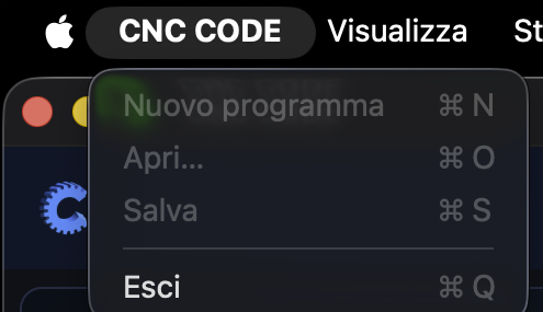
The first menu, named after the app, contains the basic functions for the current program — the same ones you'd find in a separate "File" menu on other operating systems:
| Entry | Shortcut | What does it do? |
|---|---|---|
| New Program | ⌘N | Create an empty program in the active channel |
| Open… | ⌘O | Opens a program from a file |
| Save | ⌘S | Save the current program |
| Log Out | ⌘Q | Closes the application |
4.2 View
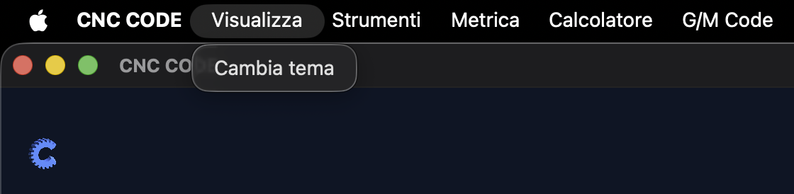
The View menu contains two items. The first, Lathe Information ABL, changes its name based on the lathe control currently open—here, for example, with a ABL lathe, it becomes "Lathe Information ABL." The second, Change Theme, is always present.
Information [machine name]
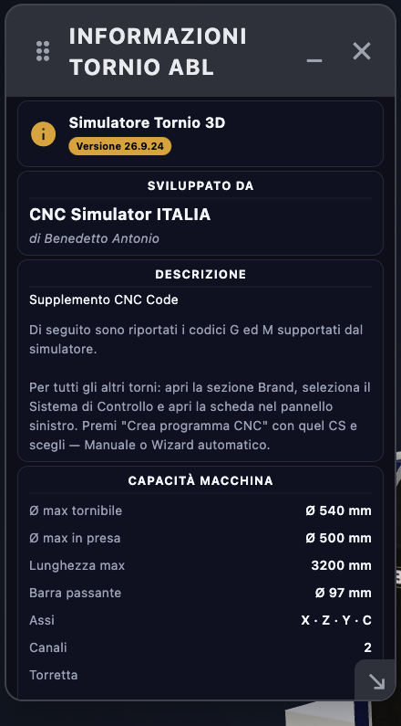
Opens a summary sheet for the active lathe: who developed it, a brief description, and the machine’s capabilities—maximum turnable diameter, maximum chuck diameter, maximum length, bar capacity, axes, and channels—the same technical sheet already seen in the Central Area (Chapter 6.2), but accessible at any time while you work, without having to return to the Home screen.
For lathes other than the standard model, the description explicitly states: open the "Brand" section in the left panel, select the control system, and open its tab—from there, create a CNC program, either manually or using the automatic wizard.
Change Theme
Toggle between dark and light themes — just like the 🎨 button in the top bar.
The difference between the two themes isn't as drastic as you might expect: the app doesn't simply flip everything from black to white. The change affects certain colors in a subtle way—background shades, panel tones, icon contrast— to adapt the interface to ambient light without disrupting the visual experience. Those accustomed to the dark theme will likely never feel the need to change it.
The preference is saved permanently and applied at every subsequent startup.
4.3 Tools
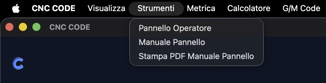
The Tools menu is the menu item in macOS primarily dedicated to educational licenses and classroom training. Here you’ll find everything you need to study and simulate working directly on the control panel of a CNC machine — those physical buttons located on the machine itself, with the same realistic functions that an operator uses every day on the shop floor.
It is the ideal tool for teachers and students who want to learn how to operate a CNC machine without having one in front of them: the button responses, the logic of the machine states, and the visual feedback—all modeled after the actual behavior of the controls.
Operator Panel
The interactive Operator Panel opens: a faithful reproduction of the physical panel located on the machine. The buttons replicate the actual functions— cycle start, stop, axis jog, feed and speed override, mode selection (AUTO, MDI, JOG, EDIT)—with a visual and logical response similar to that of a real CNC control.
It is not a simplified educational toy: the state logic mirrors that of the actual machine. Students learn where to put their hands even before they touch the machine.
Panel Manual
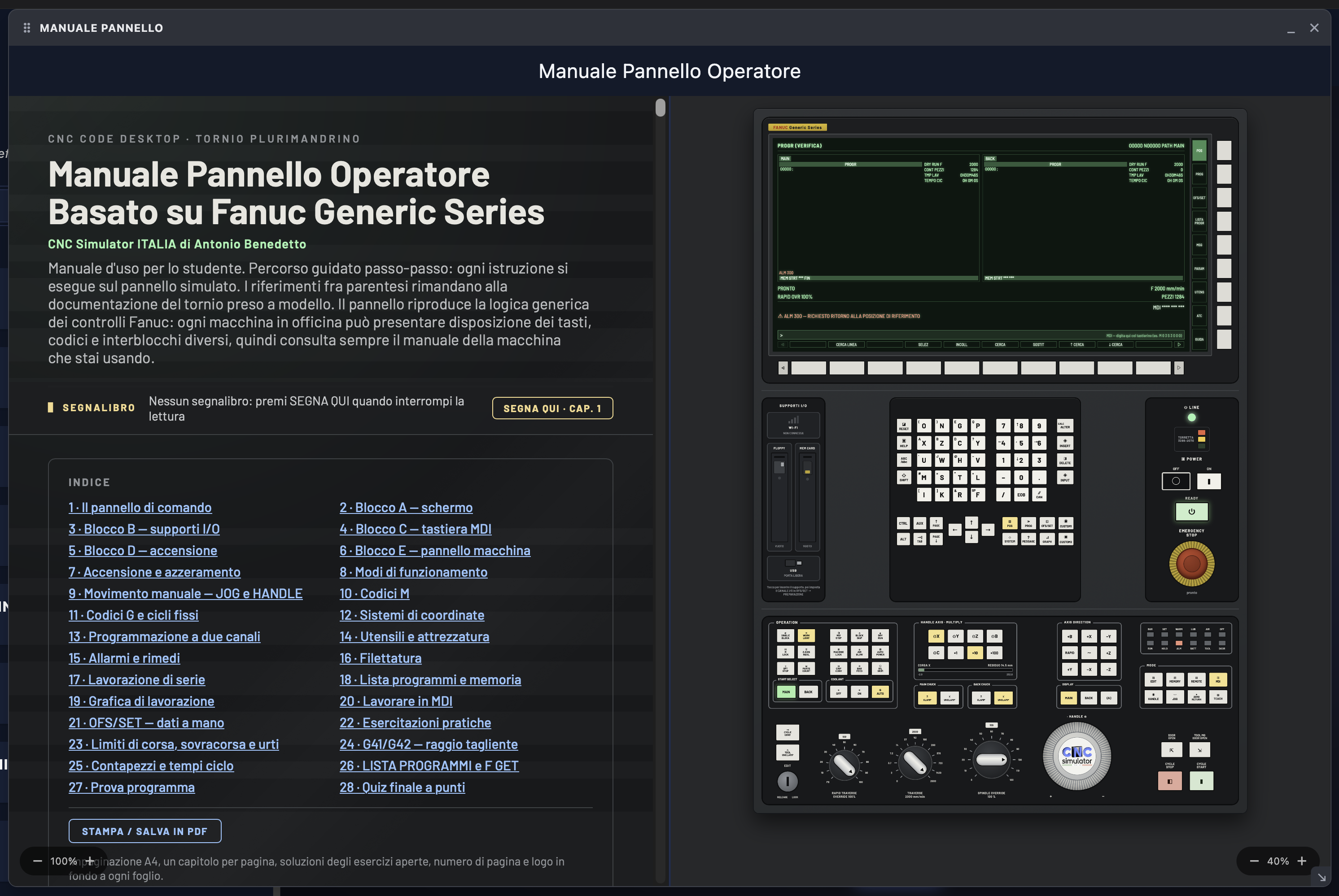
The Operator Panel Manual is the reference guide that accompanies the use of the interactive panel. It is not just a simple list of buttons: it is a structured document that explains the purpose of each function—how to use it, in which mode it is active, and what happens on the machine when you press it.
The main benefit is that it eliminates the need for on-the-job training. Those who study the manual alongside the simulated panel arrive at the actual machine already knowing where to look and what to touch—without the first-day jitters, without beginner’s errors that can be costly on CNC machines.
It is a true technical manual, based on a generic CNC-Fanucd multi-spindle lathe — not just a brief overview, but 28 sections that start with the physical hardware of the control panel and go all the way to hands-on exercises and a final quiz with a point system:
- The control panel consists of five blocks: A. Display; B. Input/Output terminals; C. KeyboardMDI; D. Power and Emergency; E. Machine Panel
- Power On and Zeroing, Operating Modes, and Manual Axis Movement — JOG and HANDLE (handwheel)
- M Codes, G-codes and canned cycles, workpiece coordinate systems, and two-channel programming
- Tools and equipment, alarms and remedies, threading, machining standard
- Program list, memory and background editing, machining graphics, MDI
- OFS/SET — manual offsets and origins, G41/G42 — cutting edge compensation, travel limits, and overtravel
- Piece counters and cycle times, how to read a program from the list using the cursor, how to run a test program
- Step-by-step hands-on exercises and a final quiz with points to test what you've learned
Print PDF Panel Manual
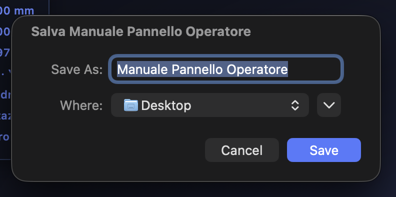
The "Print PDF Panel Manual" option generates and downloads, with a single click, the Operator Panel Manual in .PDF format, ready to be printed or distributed digitally.
After clicking the item, the system opens the operating system's print/save panel — on macOS, the native print dialog appears with the option "Save as PDF" in the lower-left corner. Choose the destination, and the file is yours, without going through a browser or external services.
Why is it useful to have it at PDF:
- Printed handouts — the instructor prints one copy for each student to bring to the classroom or lab, to keep on hand during the exercises
- Digital distribution — send via email or upload to the school's learning platform (Classroom, Teams, Moodle) before class
- Offline access — students can keep it on their phone or tablet without needing an internet connection
- Training Archive — the training center keeps it in its educational records along with the CNC exercise programs
4.4 Metrics
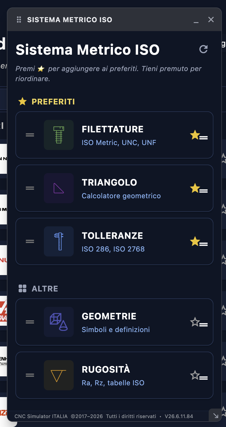
The "Metric → ISO Metric System" entry opens the technical reference guide built into the app: a collection of ISO reference tables that every programmer and CNC operator consults dozens of times a day, now available without leaving the app and without opening printed manuals or searching online.
Available tables
| Table | Standard | What is it used for? |
|---|---|---|
| Tolerances and Fits | ISO 286 | IT tolerance grades, basic positions for shafts (a→z) and holes (A→Z), tolerance values for free-fit, mixed-fit, and interference-fit fits. Essential when you need to determine machining operations based on a drawing. |
| Surface roughness | ISO 4287 / ISO 1302 | Ra and Rz values and N roughness class, showing the correspondence between the symbol on the drawing and the recommended machining process (turning, grinding, etc.). Useful for setting feeds and final passes based on the required finishing. |
| Metric threads | ISO 68-1 / ISO 724 | Pitch, nominal diameter, core diameter, and flank diameter for standard and fine-pitch metric threads. Used to calculate tapping cycles (G84/G76) and pre-tapping drilling diameters. |
| Geometries and Geometric Tolerances | ISO 1101 | All 14 GD&T symbols—form, orientation, location, runout— with their meanings and scope of application. This allows you to interpret the geometric requirements on the drawing without consulting the standards manual. |
The overlay window — keep it open at all times
This is the real advantage over a printed manual or a web page: the Metrics window opens as a separate window, independent of the main app. You can position it anywhere you want on the screen—in a corner, on a second monitor, or next to the simulator—and continue working on the CNC program without having to close it.
The typical workflow in a workshop or classroom is this: you have the lathe simulator open, you’re writing a turning cycle, and you need the shank diameter for an M16. Open Metrica, go to the thread table, read the value, and enter it into the program—all without switching windows or losing your train of thought. The window stays there, open in the background, ready for your next reference.
4.5 Calculator
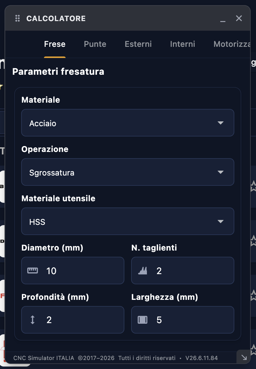
The Calculator → Cutting Calculator menu item opens the tool that eliminates one of the most repetitive tasks in CNC programming: determining the correct cutting parameters based on tool and material data. No Excel spreadsheets, no calculator, no formulas to memorize—just enter the values you know, and the app will give you the ones you need for your program.
How It Works — The Formulas Behind the Calculator
The calculator is based on the two fundamental formulas of cutting technology:
| Magnitude | Formula | Symbols |
|---|---|---|
| Spindle speed n | n = (Vc × 1000) / (π × D) |
Vc = cutting speed [m/min], D = tool diameter [mm] |
| Vf Feed | Vf = fz × z × n |
fz = feed per tooth [mm/tooth], z = number of teeth, n = rpm |
You enter the data you know—you can usually find it in the tool catalog or in the material data sheet—and the calculator solves the equations. The result is the value to be entered directly into the S block (spindle speed) and F block (feed rate) of your G-code program.
The fields in the calculator
| Field | Units | Description |
|---|---|---|
| Material | — | Select the workpiece material from the drop-down menu (steel, aluminum, cast iron, stainless steel, titanium, plastic…). It automatically sets a recommended range of Vc as a starting point. |
| Tool Type | — | Milling cutter, drill bit, turning tool, etc. Affects the reference values for fz and the number of teeth. |
| Tool diameter | mm | The diameter D of the tool. In turning, this is the diameter of the workpiece at the point of machining. |
| Cutting speed Vc | m/min | A technical parameter that depends on the tool-material combination. You can find it in the tool catalog or use the value suggested by the app. |
| Number of teeth z | — | Number of cutting edges on the tool. For drill bits, it is always 2; for end mills, it ranges from 2 to 6 or more. |
| Feed per tooth fz | mm/tooth | How far the tool advances for each cutting edge that comes into contact with the workpiece. It depends on the material, the tool, and the depth of cut. |
The Results
| Result | Units | Where is it used in G-code? |
|---|---|---|
| Spindle speed n | revolutions per minute (RPM) | Value to be entered after "S" in the spindle start block
(e.g., S1200 M03) |
| Vf Advance | mm/min | Value to be entered after "F" in the motion block
(e.g., G01 X50. F250) |
Calculator
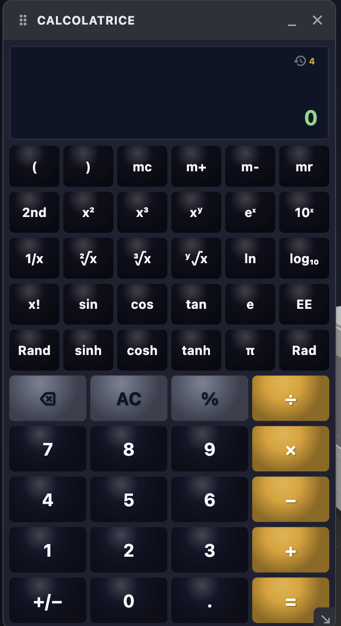
The second menu item, Calculator, has nothing to do with cutting parameters: it’s a full-featured scientific calculator, for all those quick calculations you need while programming that don’t warrant opening another app—a dimension to calculate, a trigonometric function for an angle, or a quick conversion.
In addition to the four basic operations, you’ll find trigonometric functions (sine, cosine, tangent, and their hyperbolic inverses), powers and roots (square, cube, nth), exponentials and logarithms, factorials, the constants e and π, degree-to-radian conversion, and a standard memory (mc / m+ / m- / mr) for saving a result and reusing it in the next calculation.
4.6 G/M Code
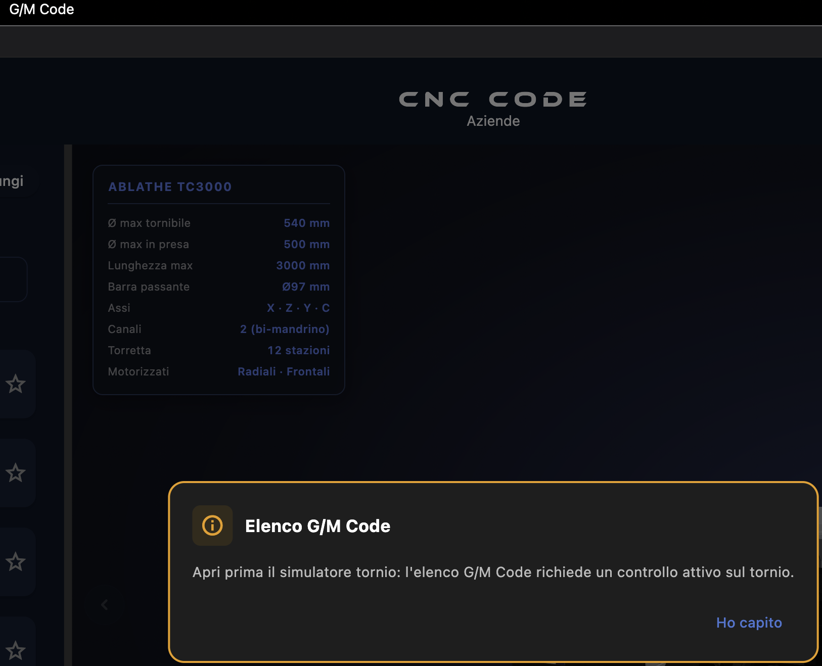
The "G/M Code → G/M Code List" entry opens the complete list of G and M codes supported by the app—including function, syntax, and usage notes—with all the details you need to program or study a specific control.
Note: It does not open from the home screen
There’s one important thing to know: this option doesn’t work if you’re on the main screen without an active machine. The reason is simple— the list of G and M codes isn’t universal; it varies completely from brand to brand and from controller to controller. A G76 on FANUC is not the same as a G76 on HAAS. An M08 on a lathe is not the same as an M08 on a milling machine. Without knowing which machine you’re referring to, the app has no way of showing you the correct list.
To access the list, you must first open a simulator—a lathe or milling machine—with a selected brand and CNC control. At that point, the "G/M Code" option in the "macOS" menu becomes available and shows you the exact codes for that machine, along with descriptions and syntax specific to that control system.
The Left Panel — Brand List
The left panel of the main screen is where it all begins: this is where you select the CNC brand you want to work with. The choice you make here determines which G and M codes are available, which simulator is loaded, and which control logic you will be working with.
5.1 List of Brands
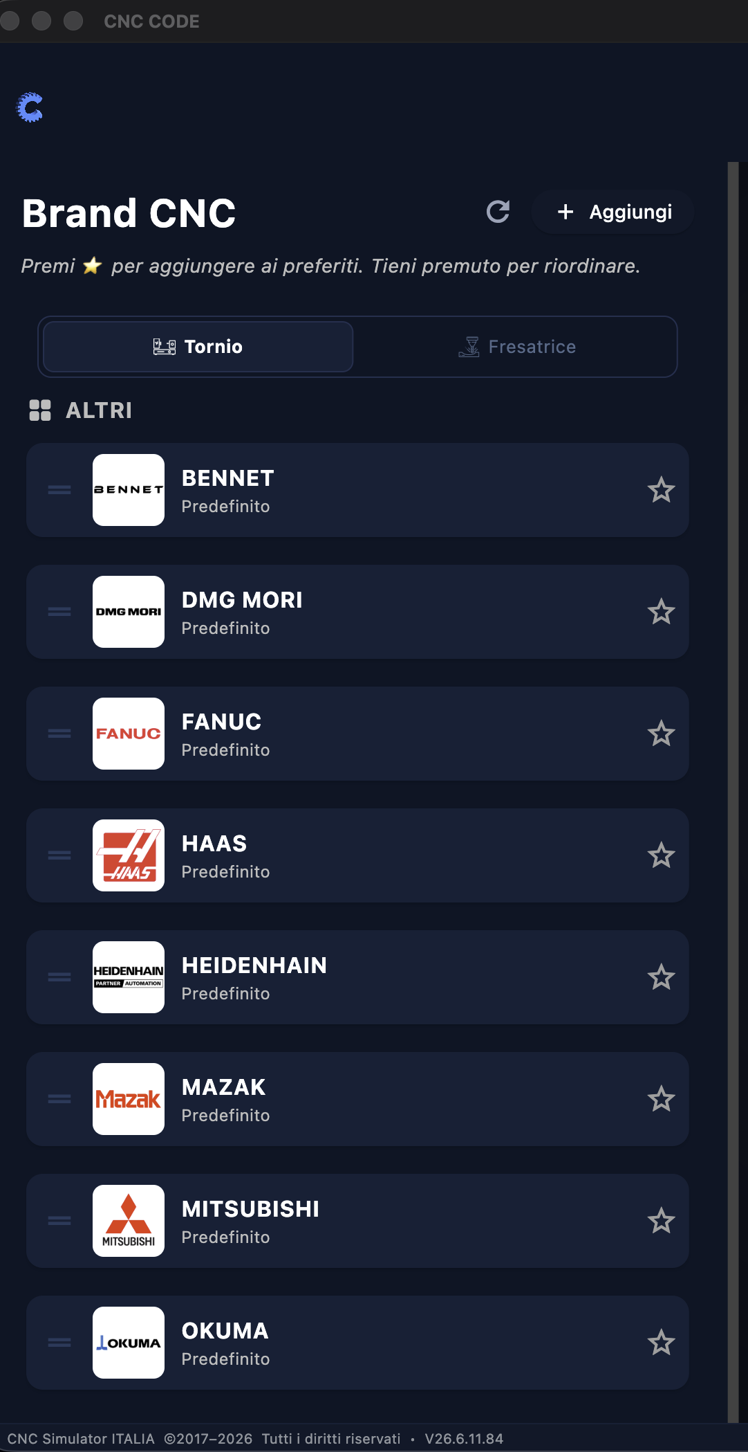
The panel displays a list of all CNC brands available in the app. This isn’t a fixed, static list: it’s a constantly growing catalog that expands whenever new customers request it. If your brand isn’t listed, just ask—it will be added and made available to everyone.
Participating Brands
The list already includes the leading manufacturers of CNC controls used in workshops and schools around the world. Among the brands included are FANUC HAAS, Siemens, Heidenhain, Mazak, Okuma, Mitsubishi, Fagor, NUM, Hurco, Brother, Doosan, and many others—each with its own G and M codes, syntax, and programming characteristics.
Lathes and Milling Machines — Two Separate Worlds
Within the same brand, you’ll almost always find two distinct categories: controls for lathes and controls for milling machines. They are not interchangeable, and it’s not a matter of preference—they are fundamentally different machines, with different programming logics, different axes, and different canned cycles.
A lathe-specific FANUC and a milling machine-specific FANUC share the basic structure of the language but then differ in everything that matters: drilling cycles change, rotary axis control changes, spindle commands change, and working planes change. By selecting the right control—lathe or milling machine—the app presents you with the exact programming environment for your machine, without any approximations.
A catalog that grows with you
The development logic behind CNC Code is simple: the brand catalog grows based on user requests. If a repair shop has a machine with a control system not yet included in the app, it can submit a request through the Support section— the team assesses the availability of technical documentation and, if feasible, adds the control. Once available, all users will find it updated in the list without having to do anything.
This applies in particular to the "Custom" checks for Enterprise licenses: checks tailored to a specific machine, including all of the manufacturer’s proprietary cycles. These remain private and visible only to the company that requested them— but the list of standard brands is shared and grows for everyone.
5.2 A Brand's Controls
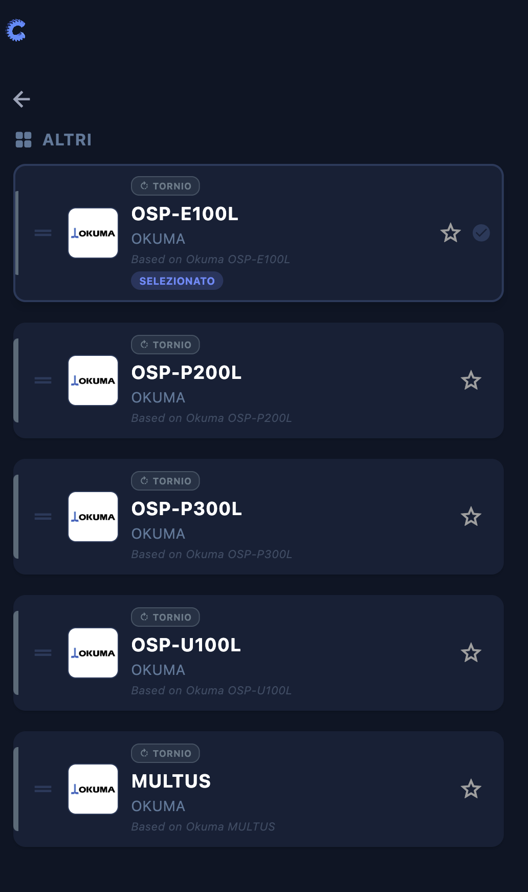
When you select a brand from the left-hand panel, the app displays a list of the controls available for that manufacturer. A control is the specific version of the CNC system installed on the machine—and it is at this level that the differences that really matter in programming come into play.
Why are the checks different from one another?
Two lathes from the same brand are not necessarily programmable in the same way. A lathe with FANUC 0i-TF and one with FANUC 31i-B share the same base, but the 31i supports advanced cycles, C-axis machining operations, spindle synchronization, and functions that simply do not exist on the 0i simply do not exist. Writing a program designed for the 31i on a machine with the 0i can cause errors—or worse, unexpected behavior.
That's why CNC Code distinguishes between controls one by one: by selecting the exact control for your machine, you work in an environment that accurately reflects that specific firmware version, with the available cycles, the correct syntax, and the actual limits of that machine.
What Changes from One Checkup to the Next
| Appearance | Practical Example |
|---|---|
| Available Canned Cycles | G76 multi-pass threading is present on the 31i, but is absent or different on older versions |
| Rotary Axis Control | C-axis and live tooling are available only on high-end lathe controls |
| Parameter Syntax | Some controls use different letters for the same parameters (e.g., Q vs. K in some cycles) |
| Special Features | G68.1 tilted plane, G96 constant cutting speed, M500/M501 synchronization — available only on specific controls |
| Tool Correction | The handling of length and radius offsets varies between versions and between lathes and milling machines |
How to Choose the Right Control
The control installed on your machine is indicated on the physical panel—usually on the display or on a label inside the cab. If you don't remember, you can also find it in the machine manual or the manufacturer's documentation. If you’re unsure between two similar versions, choose the more conservative one—the basic cycles work on all versions, while the advanced ones work only on versions that support them.
5.3 Important Information — Be sure to read it, every time
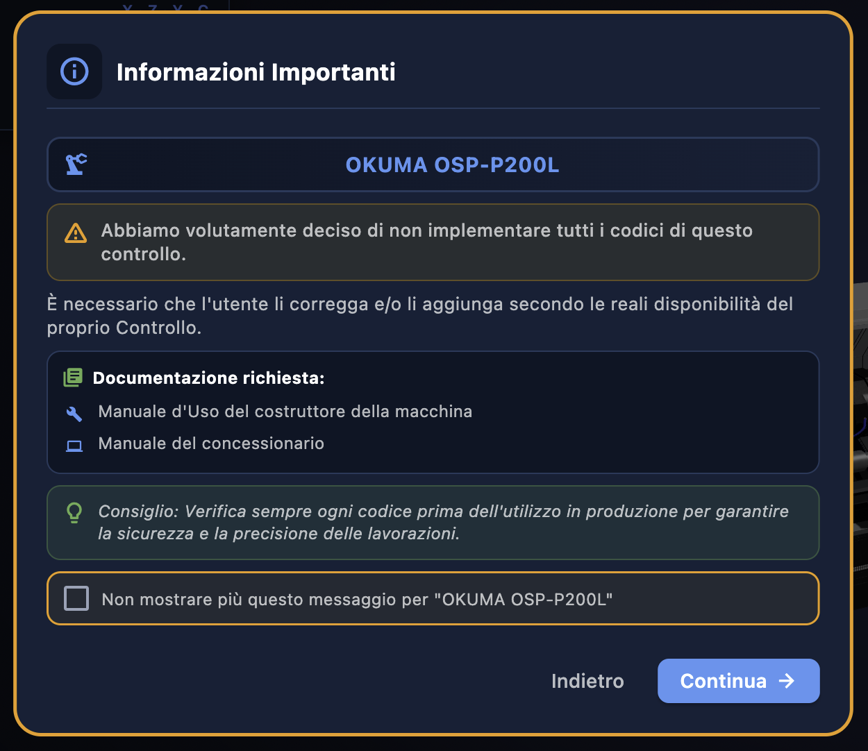
When you select a control for the first time, the app displays this pop-up: Important Information. It is not an error message, nor is it a formality to dismiss quickly—it is a notice worth reading carefully every time you work with a new control.
Why this choice?
CNC controls from major manufacturers are massive systems, documented in hundreds of pages of technical manuals that vary from version to version, from market to market, and from configuration to configuration. Two machines with the same control name printed on the panel may have different capabilities because one is configured with additional software options and the other is not.
Implementing all the code for all controls in their most comprehensive form would mean including functions that simply do not exist on many real machines — creating a false sense of security. A programmer who spots a loop in the app and uses it in production on a machine that doesn’t support it can cause errors, alarms, or worse.
That is why we have chosen the honest approach: we implement the solid, well-documented core of each test and inform the user that the rest must be verified on their own specific machine. CNC Code is a support and training tool, not a substitute for the manufacturer’s official documentation.
What to Do in Practice
The pop-up indicates the documentation to consult:
- Machine manufacturer's user manual — the original manual from the control manufacturer (FANUC, Siemens, Okuma, etc.), which describes all the codes supported by that firmware version
- Dealer's Manual — the manufacturer's specific manual for the machine (Mazak, DMG Mori, Doosan, etc.) that adapts the basic control system to that particular machine by adding or removing functions
If you have both, you'll have a complete picture of what you can and cannot do on that machine. Any code not found in these manuals should not be used in production, regardless of what the app shows.
Don't show this message again
At the bottom of the pop-up, you'll find the box "Don't show this message again for [control name]". If you check the box, the notice will no longer appear for that specific check in subsequent sessions—but only for that one. For every new check you open for the first time, the pop-up will reappear. This is intentional: each check has its own unique characteristics, and the notice is useful every time you enter uncharted territory.
5.4 The Code List — G Codes, M Codes, and Aux Codes
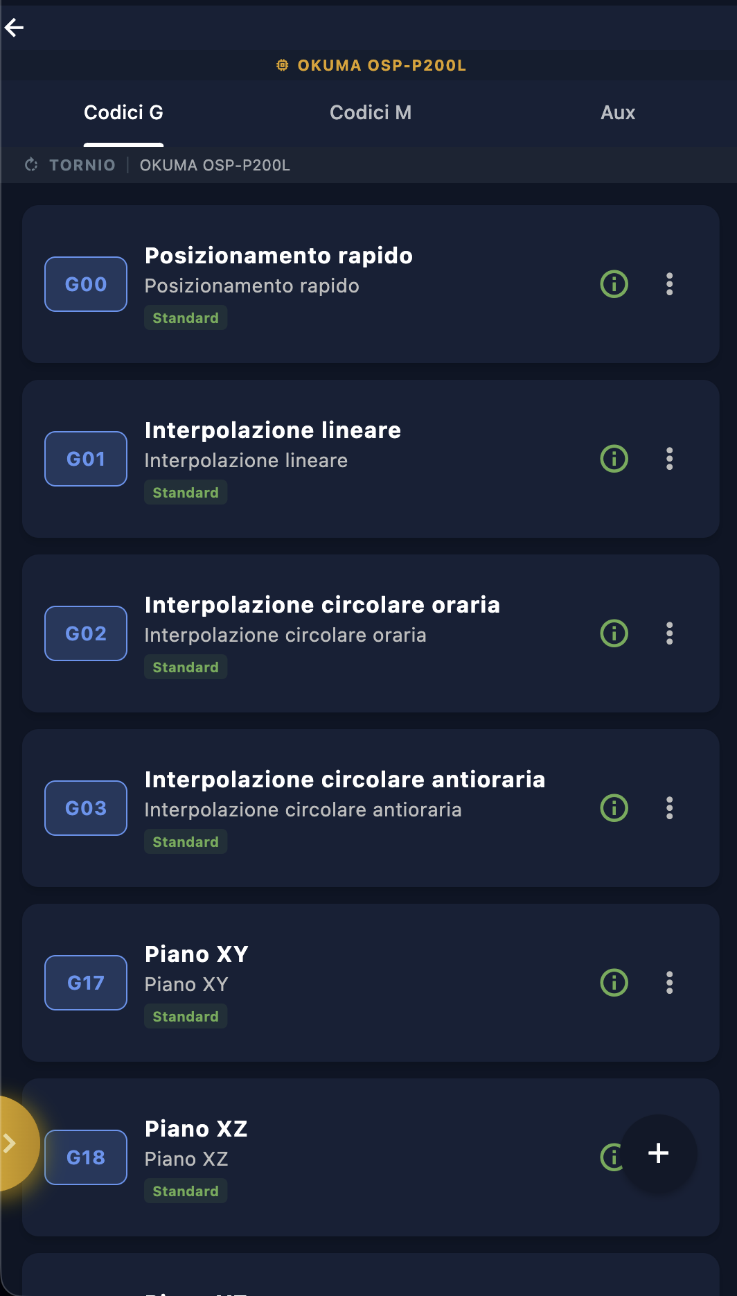
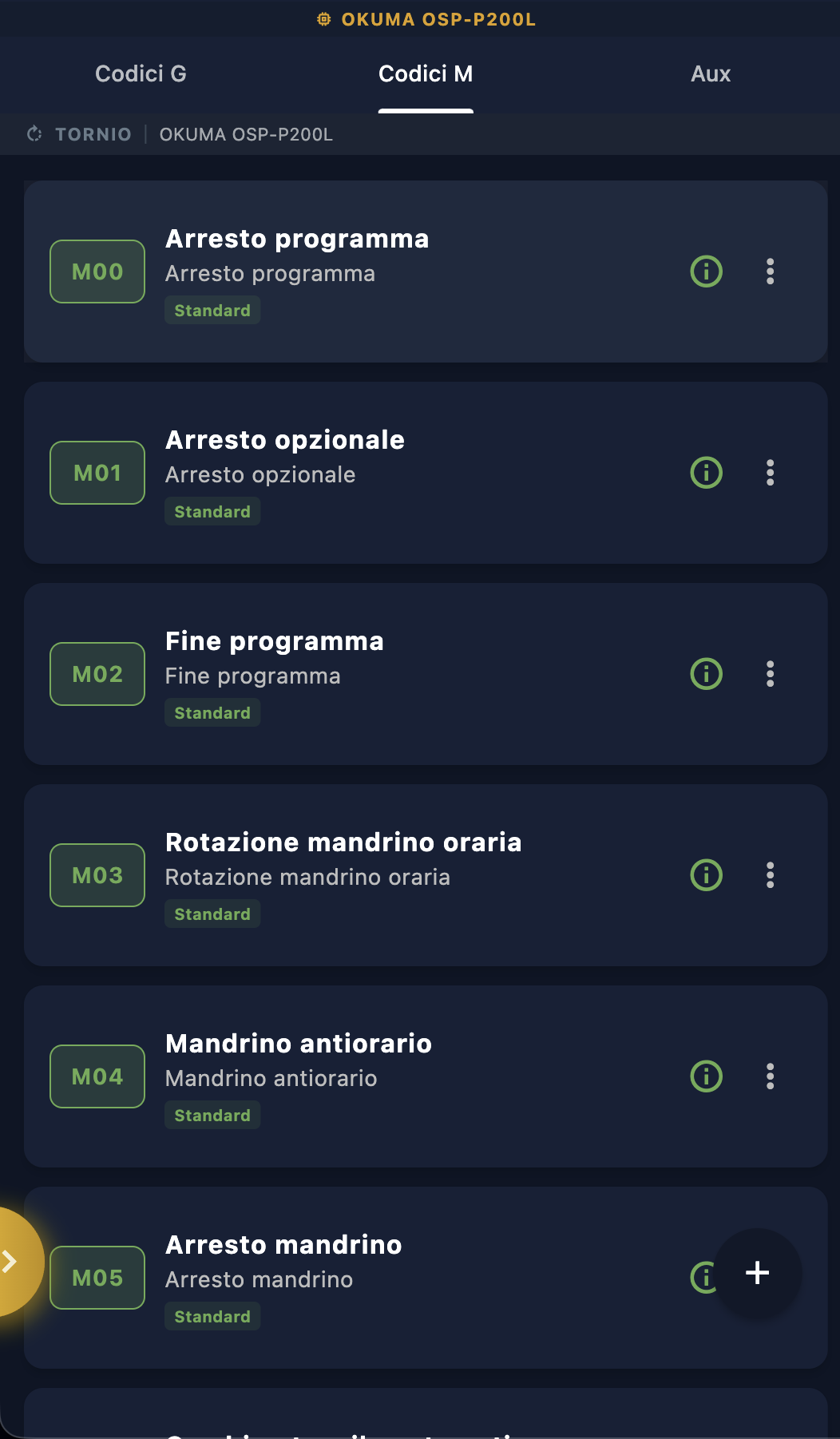
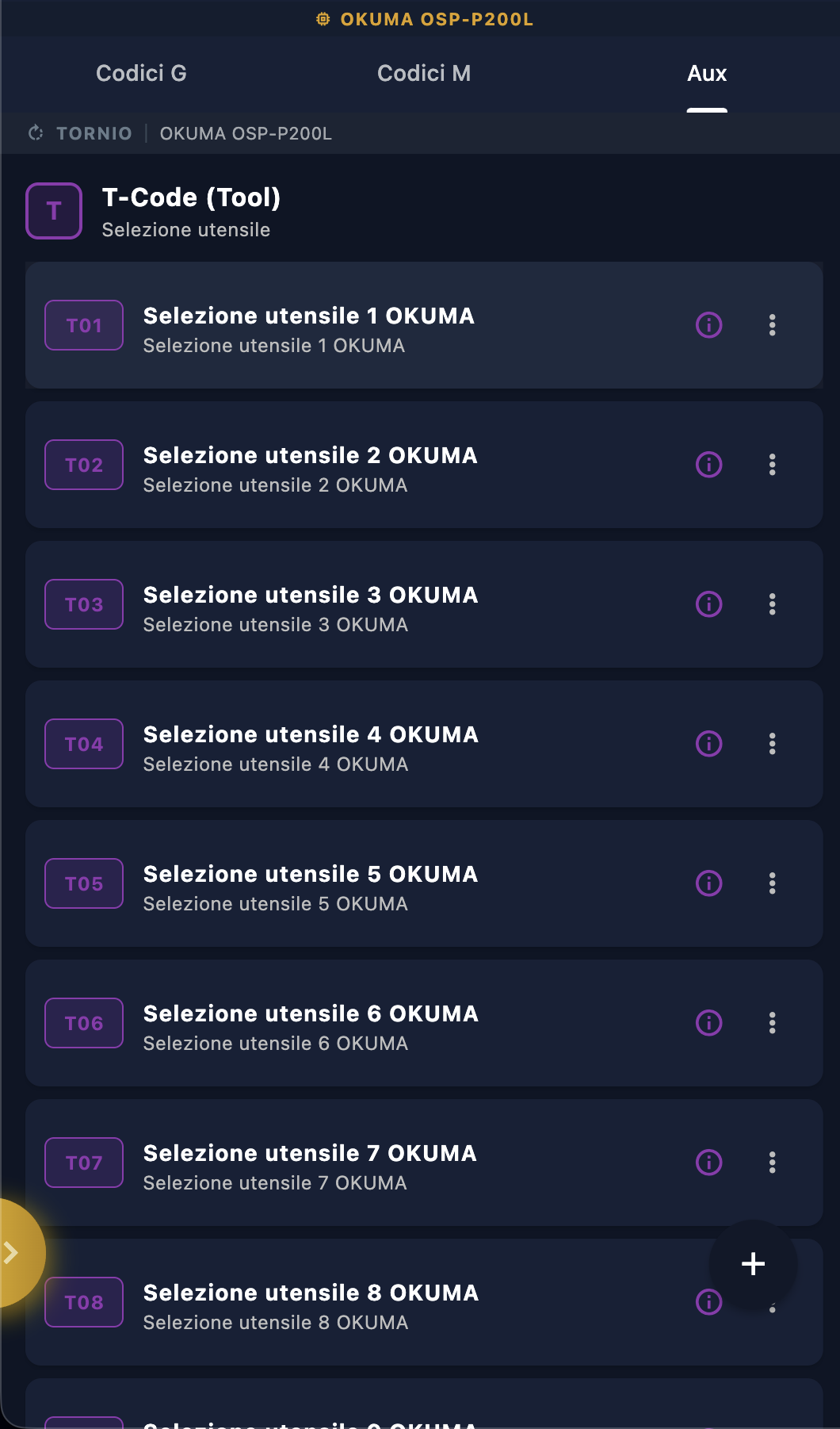
Once you've selected the control and closed the "Important Information" pop-up, the app opens theList of Codes of that machine. It is organized into three separate tabs — G Codes, M Codes e Aux — each with its own identifying color and its own logic.
G codes — in blue
The "G Codes" tab lists all the motion and preparatory function commands for the selected control. Each entry displays the code (G00, G01, G02…), the function name, and a brief description. The “Standard” badge indicates that the code is part of the app’s implemented and documented core functionality.
G-codes are at the heart of CNC programming: they define how the tool moves—in rapid traverse, linear interpolation, and circular interpolation— and activate the machine’s operating modes, such as canned cycles, working planes, tool radius compensation, and much more.
M Codes — in green
The "M Codes" tab lists miscellaneous commands—those that control the machine's auxiliary functions: spindle start/stop (M03, M04, M05), program stop (M00, M01, M02), coolant (M08, M09), automatic tool change, and everything else not directly related to axis movement. The color green visually distinguishes them from G-codes at a glance.
Aux — in purple
The Aux tab contains the control-specific auxiliary codes— primarily the T-codes for tool selection, whose syntax varies significantly from brand to brand and sometimes even among models from the same manufacturer. Here you’ll find the entries T01, T02, T03… each with a specific description of how that control system handles tool changes and the associated offsets.
The color purple distinguishes this category from the other two groups and serves as a reminder that these are auxiliary but essential commands—without proper handling of the T-Codes, nothing will work.
5.5 Breakdown of Each Item
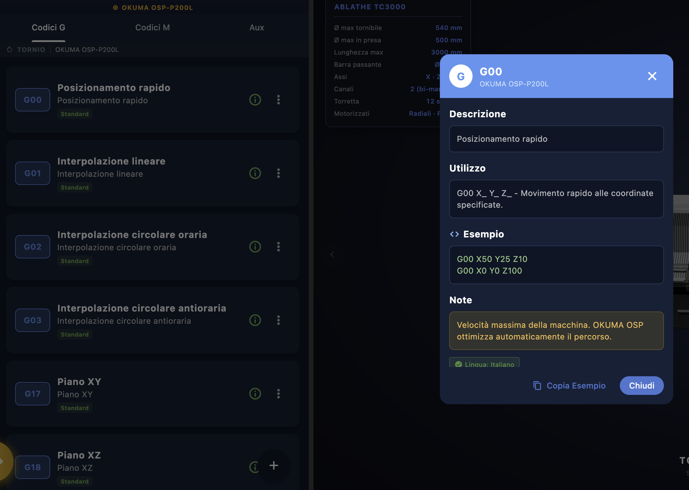
By tapping the icon ⓘ Clicking on any item in the list opens the code details panel. It's not just a tooltip—it's a comprehensive tab that contains everything you need to use that code correctly, without having to consult external manuals.
Header
At the top, you'll find the code badge (e.g., G for G-codes, M for M-codes, T for T-codes) alongside the code name and the control system it belongs to— so you always know exactly which code's data sheet you're reading and on which machine it is valid.
Description
A concise description of the code's function—in one line, no frills. It's the answer to the question "What does this code do?" For G00: Rapid positioning. Clear, immediate—that's all you need.
Usage
The syntax for using the code—how it is written in the G-code program, including all the parameters it accepts. For G00, the syntax is:
G00 X_ Y_ Z_ - Movimento rapido alle coordinate specificate.
Parameters with an underscore (X_, Y_, Z_)
indicate fields that must be filled in with actual numerical values. This section tells you
exactly what to enter and in what order.
Example
One or more ready-to-use code blocks—real, syntactically correct examples for that specific control. For G00:
G00 X50 Y25 Z10
G00 X0 Y0 Z100
The examples are not generic—they are specific to the selected controller. A G00 command on an OKUMA OSP-P200L may have a slightly different syntax than a G00 command on FANUC 31i, and the app reflects this difference.
Notes
The notes are the most valuable workpiece of the data sheet. They contain information specific to that control that you would never find in a generic G-code manual—special behaviors, limitations, warnings, and manufacturer-specific optimizations. For G00 on OKUMA OSP:
The notes vary from control to control for the same part number. What applies to OKUMA does not necessarily apply to FANUC or HAAS—which is why each sheet is specific to the selected control.
Language: Italian
The ✅ Language: Italian badge at the bottom of the card indicates that the description, usage, and notes are available in the language currently selected in the app. If you change the language in Settings, the entire card updates accordingly—same card, nine languages.
Copy Example and Close
The "Copy Example" button copies the example code shown on the tab to the clipboard—ready to be pasted directly into the program you are writing. No need to copy it by hand, and no transcription errors. The "Close" button closes the panel and returns you to the list.
5.6 The "Get This Control" tab
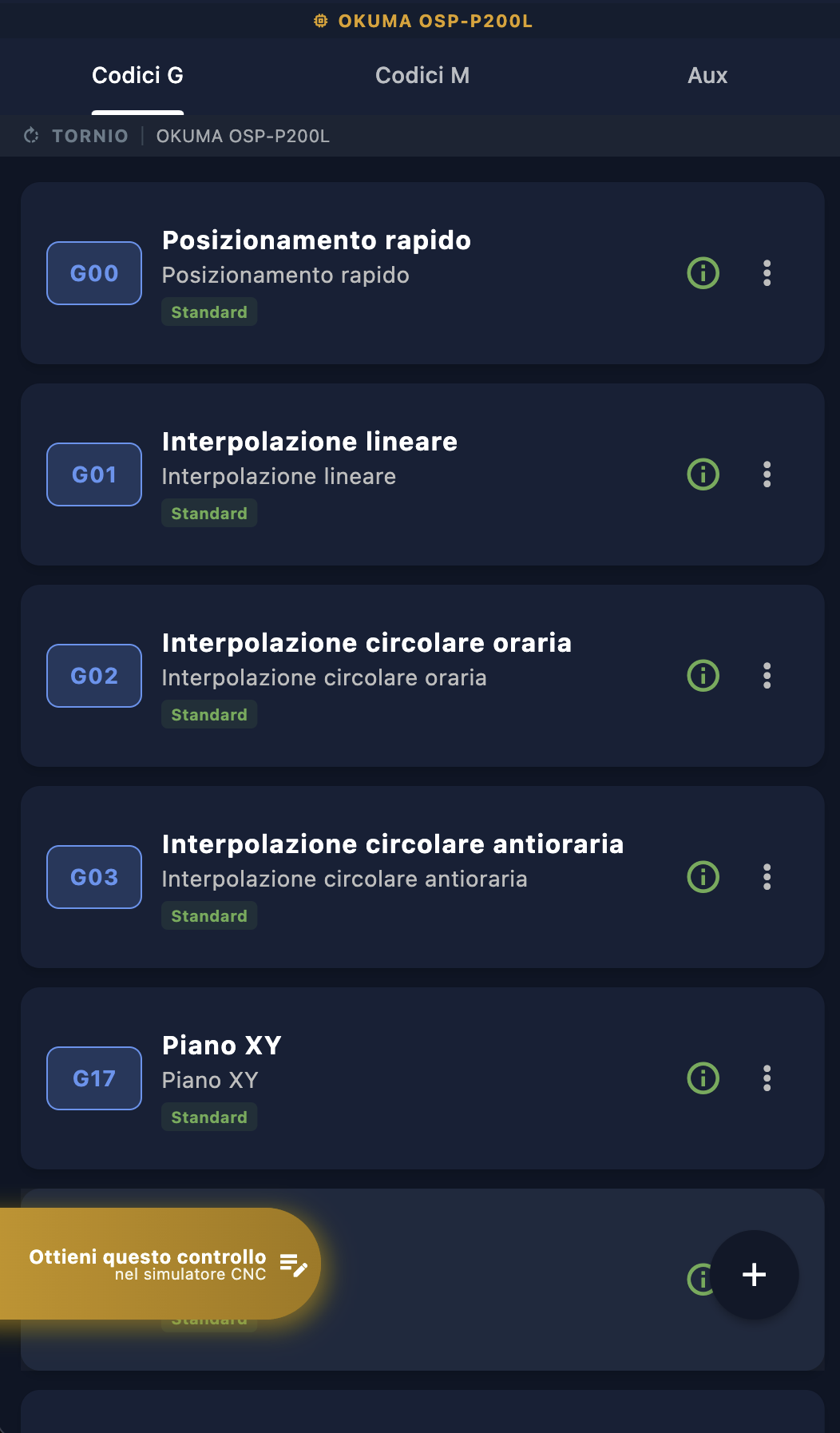
As you scroll through the list of codes for a check, a orange tab with the words "Get this control in the CNC simulator". It's not an ad banner—it's a direct link to one of the app's most important features: the Custom Checks.
The tab is activated by touch and behaves differently depending on the situation you're in.
If you don't have this control yet
Tapping the tab opens the purchase dialog for the Custom for that specific machine. A “Custom” controller is the version of the simulator custom-built for that specific controller—featuring the manufacturer’s proprietary cycles, the exact syntax, and the actual parameters of your machine. It’s not the standard version from the catalog, but a simulator that is 100% faithful to the controller you have in your workshop.
From that dialog, you can see what's included in the checkup, view the price, and proceed with the purchase without leaving the app.
If you already have an active check
If that check has already been purchased and activated on your account, the tab opens a management dialog where you can decide what to do: open the simulator directly, view the details of the active check, or access the available options.
We will examine both cases in detail—purchase and active control— in the next section.
5.7 Purchase of "Custom" — Dialogue Between Students and Teachers
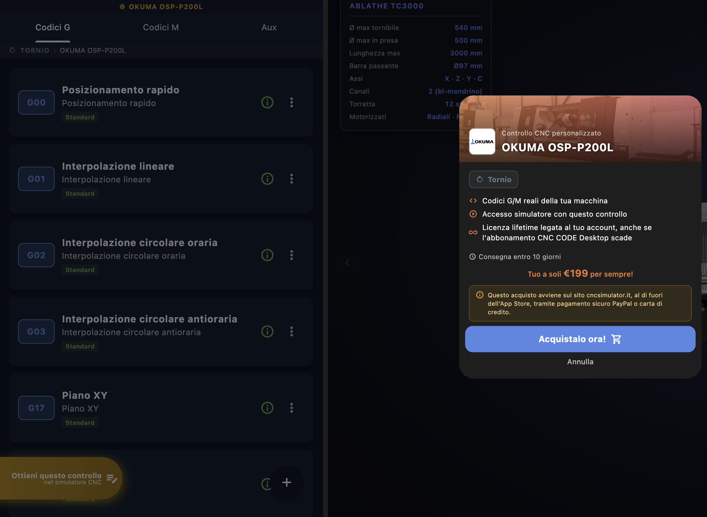
Tapping the orange tab on a control you haven't purchased yet opens this dialog: the purchase page for the "Custom" control for that specific machine. Everything you need to know before purchasing is right here, on a single screen.
What Does a "Custom" Inspection Include?
| Function | Details |
|---|---|
| Your Car's Actual G/M Codes | Not the generic list from the standard catalog—the actual codes for that control, along with the manufacturer's proprietary syntax, parameters, and cycles |
| Access the simulator using this control | The lathe or milling machine simulator is loaded with the logic for that specific control, not with the generic logic FANUC/base |
| Lifetime License | Linked to your account forever—even if your CNC Code Desktop subscription expires, Custom Control remains yours and accessible |
| Delivery within 10 days | The control unit is manufactured and shipped within 10 days of purchase — it is not an automatic download but an actual machining process based on technical documentation |
Who It's For — and Profile Limits
Custom is designed for three categories of users: businesses, individuals, and schools. The purchase process varies depending on who you are and which device you’re using to make the purchase—not just based on your profile.
The price shown in the dialog box—in the example, €199 for life— is the fixed, one-time price for that check, with no recurring fees. But before proceeding, it’s important to know how many “Custom” checks you can purchase:
| Profile | From a phone | From a tablet or desktop |
|---|---|---|
| Private | Up to 2, for a fee | Up to 2, for a fee |
| Teacher / School | Up to 2, for a fee | Up to 2, for a fee |
| Company | Up to 2, for a fee — as a private individual | Unlimited, based on a quote (see 4.8) |
Individuals and teachers (as well as companies over the phone) purchase directly through the chat — fixed price, immediate payment, no red tape. The limit of 2 scans is intended for individual use: anyone with multiple devices to cover is a business, and the business profile on a tablet or desktop is designed specifically for that purpose.
How Payment Is Processed
The dialog box clearly states: "This purchase is made on the website cncsimulator.it, outside of theApp Store, via secure payment at PayPal or by credit card." After clicking “Buy Now!”, you’ll be redirected to the website to complete the payment—the check will then be activated in your account and become available in the app within the specified delivery time.
Businesses follow a different process—with a dedicated dialogue and the option to request a customized quote. We'll take a look at this right away in the next section.
5.8 Custom Audit for Businesses — Request a Quote
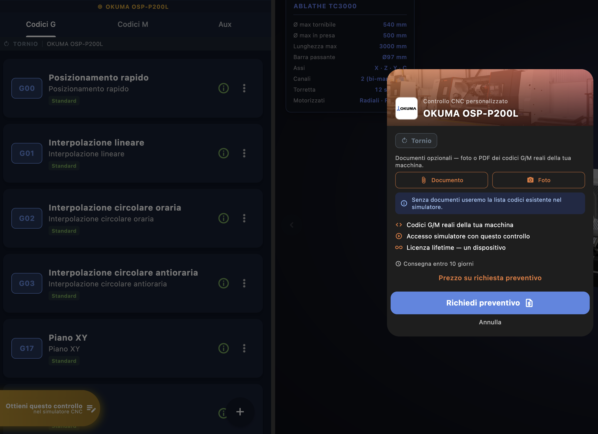
For businesses, the process is different from that for individual customers: there is no fixed price and there is no “Buy Now!” button. The process is tailored to your needs—because a Customal audit for a business is a genuine technical integration project, not a standard off-the-shelf product, and the price depends on the complexity of the audit, the available documentation, and the level of detail required.
Attach the documents for your car
Before submitting your request, you can attach the machine's technical documentation— the most important step in ensuring a 100% accurate inspection. You'll need two types of documentation, both of which are important:
| Button | What to Include |
|---|---|
| 📎 Document | The machine's G/M codes—programming manual available at PDF or, if you don't have it, photos of the pages—showing the exact brand and control system covered by this offer. These documents contain the complete list of codes, along with syntax, parameters, and manufacturer-specific notes. |
| 📷 Photo | A series of photos of the car's interior—the more you have, the better: we need them to understand the available space and the car's actual layout, not just the part numbers. Photos taken with a phone are fine, too, as long as they follow a logical order (e.g., from left to right, from top to bottom). |
What's Included in the Enterprise-Custom
| Function | Details |
|---|---|
| Your Car's Actual G/M Codes | Based on the technical documentation provided — proprietary cycles, manufacturer-specific dialects, syntax variations not found in the standard version |
| Access the simulator using this control | The simulator loads using the logic of that specific control |
| Lifetime license — one device | Permanently linked to the company account. Unlike personal accounts, the company license is managed centrally and can be assigned to devices in the department |
| Testing in about 40 days | Directly on your company's computer, with dedicated remote support via Supremo — see the complete process below |
How It Works, Step by Step
Unlike a private purchase, there is no set price here: the process is tailored to your needs, and it doesn't end with an immediate payment.
| Step | What Happens |
|---|---|
| 1. Application and Documents | Click "Request a Quote" and attach the G/M codes and interior photos (see above). You'll receive a confirmation email right away—no payment is required at this stage. |
| 2. One of our technicians will contact you | We'll review the documentation and work with you to agree on an initial solution that we can evaluate together |
| 3. Testing — approximately 40 days | Custom is tested directly on your company's computer, with dedicated remote support via the Supremo software—you can verify this for yourself, in real time, before considering it delivered |
Companies that submit requests from tablets or desktops can request custom checks with no quantity limit — Every machine in the department can have its own dedicated simulator. No forms to fill out by hand, no emails to write: just press Request a Quote The request is sent immediately with your account information and the attached documents.
The Central Area — A Sneak Peek at the Machine
In the center of the main screen, between the brand panel on the left and the right edge of the window, you'll find the Central Area: the preview of the CNC machine you're about to open. Here you’ll see the technical specifications, the 3D model that you can rotate with the mouse, and the button that launches the simulator itself.
6.1 Overview
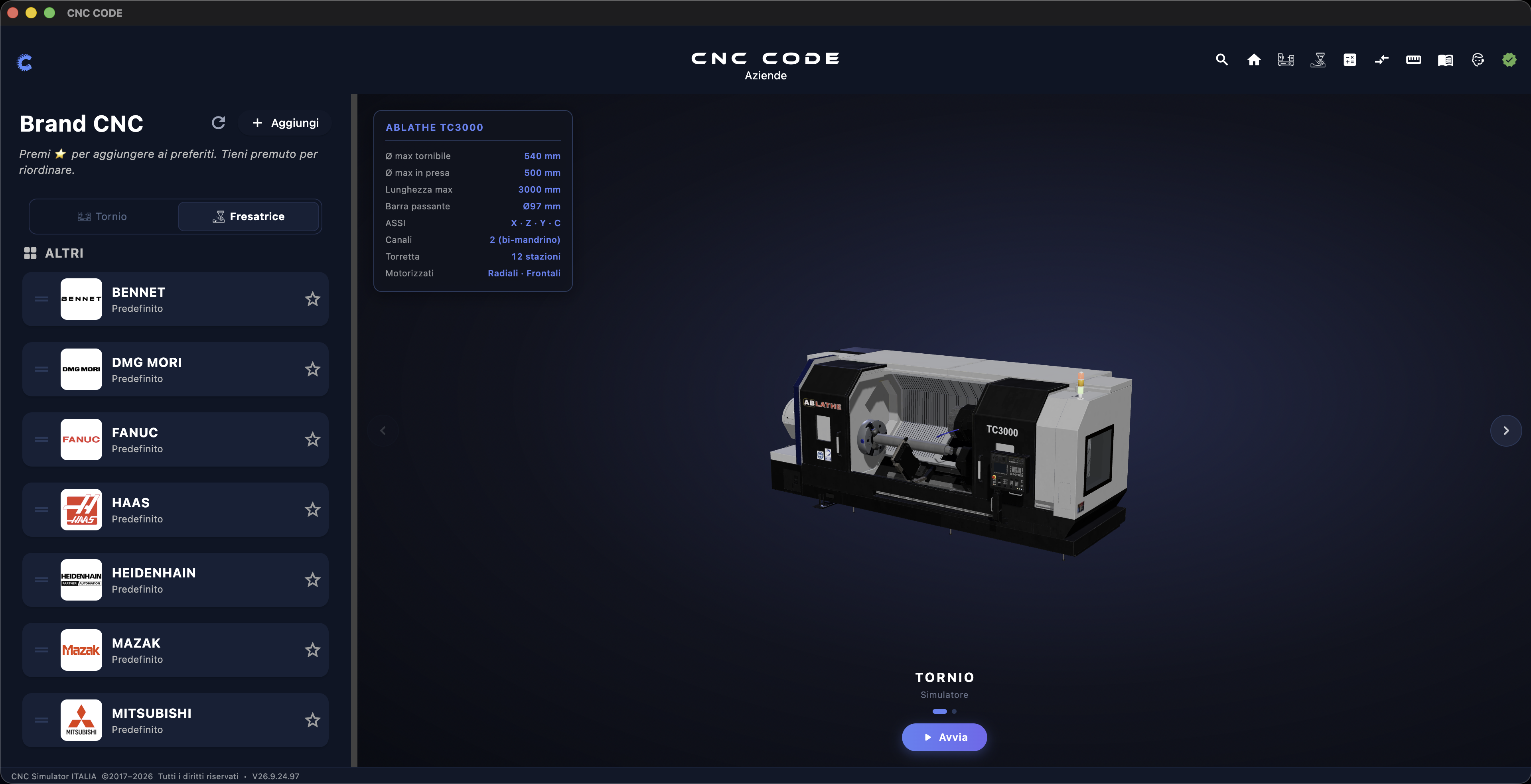
Every time you select a brand from the left panel, the Central Area updates to show you the corresponding machine: a 3D rendering of the lathe or milling machine, a technical data sheet with the main specifications, and a large "Start" button to launch the simulator with that configuration. This is where you decide what to open even before entering the work screen.
6.2 The Machine's Technical Specifications
The upper-left panel of the Central Area displays the brand name and model, followed by the machine’s key technical specifications. The fields vary slightly depending on whether you’re looking at a lathe or a milling machine, but the logic is always the same: a quick glance at the machine’s actual dimensions and capabilities before opening it in the simulator.
| Field (lathe) | What does this mean? |
|---|---|
| Max. turnable diameter | Maximum diameter that the lathe can machine above the carriage/bed |
| Max. grip diameter | Maximum diameter that the spindle jaws can clamp |
| Maximum length | Maximum travel along the Z-axis |
| Through-bar | Maximum bar diameter that can pass through the hollow spindle |
| ASSI | The axes available on that machine (X, Z, and, if present, Y and C) |
| Channels | One or two channels — two means a counter-spindle, with dual-spindle machining |
| Turret | Number of tool stations available on the turret |
| Motorized | Type of power tools supported (radial, front-mounted, or both) |
On a milling machine, the specifications vary accordingly: X/Y/Z-axis travels, table dimensions, number of tool magazine positions, and so on. In both cases, the data sheet gives you an immediate idea of what kinds of machining operations you can simulate on that machine, without having to open it up to find out.
6.3 The 3D Rendering — Rotate It with the Mouse
The model of the machine in the center is not a static image: it is an interactive 3D rendering. Click and drag with the mouse to rotate it and view it from every angle—this is useful for getting an idea of what the actual machine looks like, the size of the cab, and the layout of the spindle and turret, even before you enter the simulator itself.
6.4 The Carousel — Browse the Cars
Below the rendering, the category name (LATHE or MILLING MACHINE) and the word “Simulator” confirm which type of machine you are about to open. If multiple models or configurations are available for that brand, two navigation arrows (‹ and ›) appear on either side of the rendering: use them to scroll through the available machines. The dots immediately below the machine’s name indicate how many pages are in the carousel and which one you’re on—the filled-in dot indicates the current page.
6.5 The Start Button
The large ▶ Start button below the carousel is the final step in the entire Central Area: press it once you've selected the machine. The app opens the simulator—a lathe or milling machine, depending on what you were viewing—with the standard G/M codes for that control. From there, you enter the actual work screen and can proceed with developing your project: writing the program, simulating it, and verifying it. This is the screen we’ll examine in detail in the following chapters.
The Lathe Simulator
When you press "Start" on a lathe, you'll enter the work screen: here you write the program, simulate it in 3D, and control the machine exactly as you would at the panel of a real lathe. This is the screen where you’ll spend most of your time—let’s go through it step by step.
7.1 Overview of the Work Screen
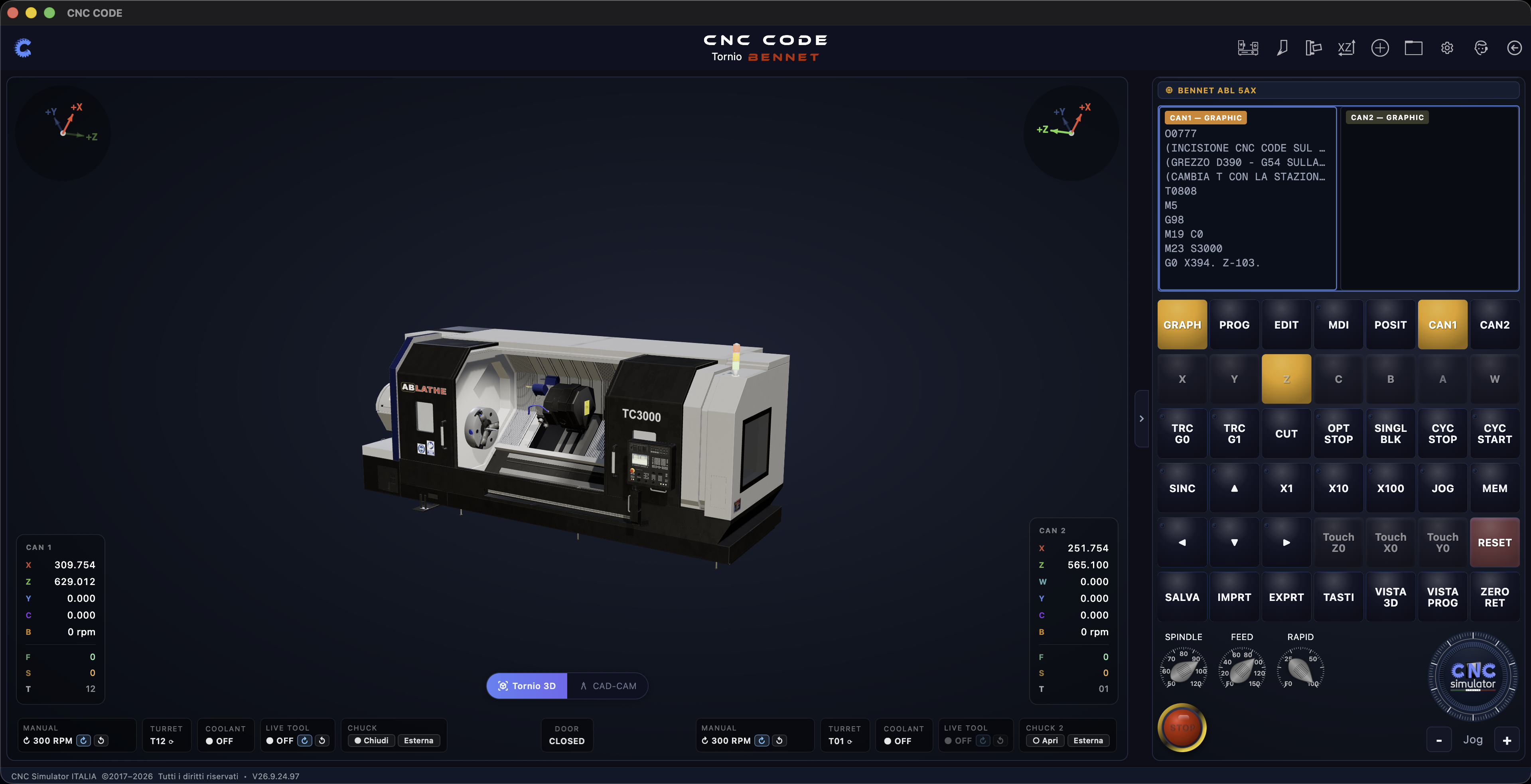
The layout is always the same, whether you're looking at a single-spindle lathe or — as in this example — a lathe with counter-spindle two channels. In the center, the 3D viewer by car; on either side, the position indicators for each channel; on the right, the program editor and the control panel; at the top, the toolbar. We'll look at them one by one in the following sections.
7.2 The 3D Viewer
The centerpiece of the screen is the 3D rendering of the machine, which is constantly updated in real time as the program runs: the spindle, turret, tailstock, or counterspindle actually move, exactly as commanded by the G-code. As in the Central Area (Chapter 6), you can rotate the view with the mouse to observe the machining process from any angle.
In the upper-left corner (and, on dual-channel machines, also on the right) you'll find the axis compass: a small, colorful triangle that always shows how X, Y, and Z are oriented relative to the current view—useful for keeping your bearings when you rotate the car.
7.3 Position Indicators — Channel 1 and Channel 2
In the two lower corners, you'll find the position panels, one per channel. On a single-spindle lathe, you’ll see only one; on machines with a sub-spindle, as in this example, there are two—one for the main turret (CAN 1) and one for the sub-spindle (CAN 2).
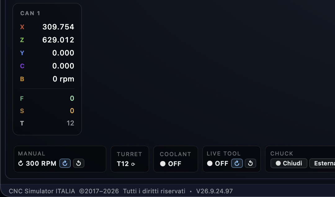
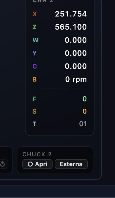
Each panel displays the current coordinates of that channel's axes (X, Z, and, if present, Y, C, B—the swivel axis of the sub-spindle), followed by F (feed), S (spindle speed) and T (active tool). Below, a compact status bar lets you see at a glance what the machine is doing at that moment: the spindle speed (MANUAL, with the buttons to turn it by hand), which station has the turret, if the coolant is on, if a power tool is active, and the status of the jaws (open/closed, indoor/outdoor).
7.4 The Views — GRAPH, PROG, EDIT, MDI, POSIT
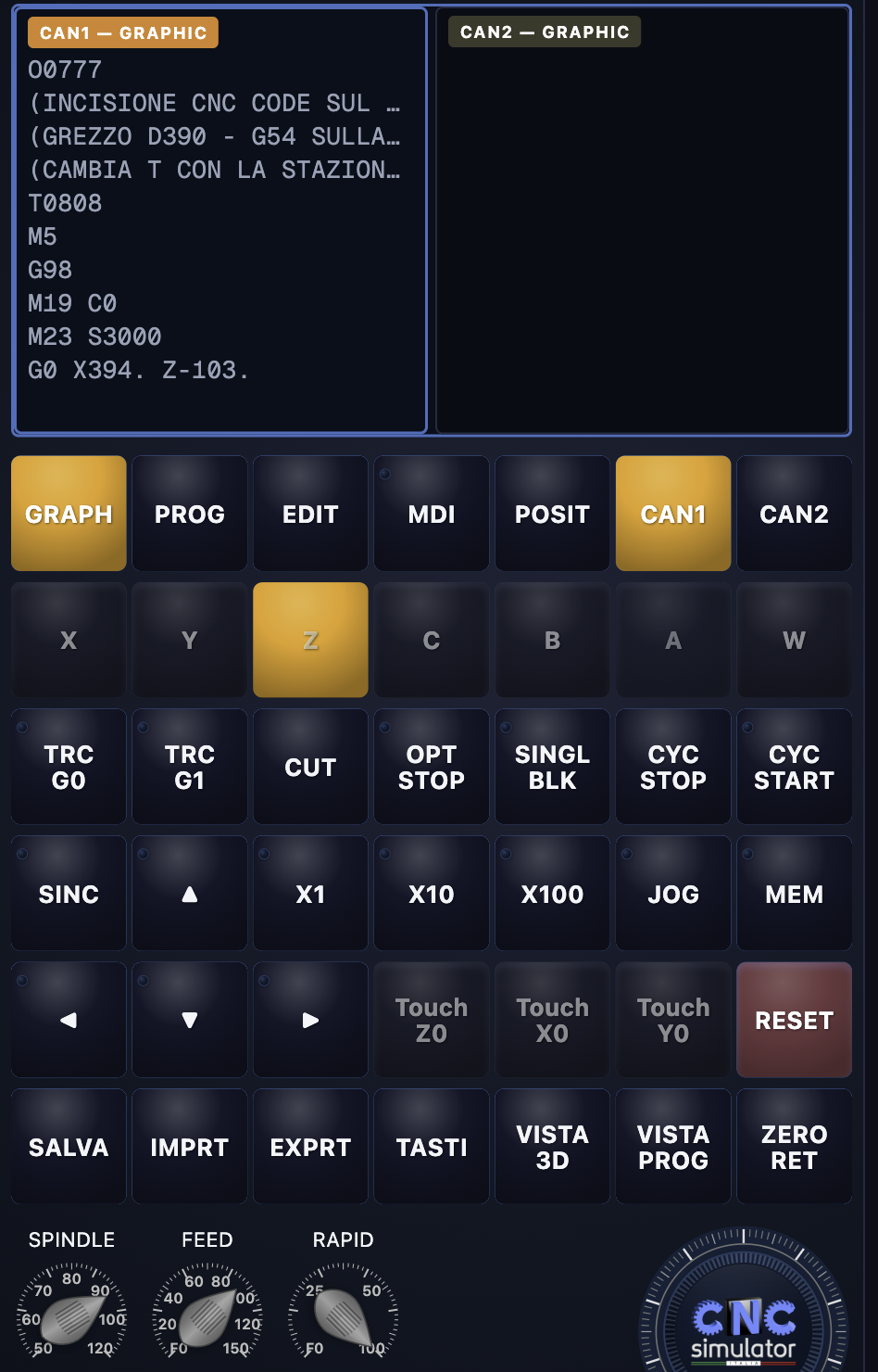
The row of five buttons above the control grid changes what you see in the editor pane at the top:
| View | What it shows |
|---|---|
| GRAPH | The active view in this screenshot—the running program displayed side-by-side with the 3D viewer, so you can follow, line by line, what the machine is doing |
| PROG | The list of available programs, so you can choose which one to load |
| EDIT | The full-featured editor for writing or editing the program line by line |
| MDI | Manual Data Input — Run a single block of code on the fly, without loading an entire program |
| POSIT | A view dedicated to coordinates, enlarged compared to the compact pane that is always visible at the bottom |
The two columns in the editor—CAN1 — GRAPHIC and CAN2 — GRAPHIC in this example—display the program for each channel side by side: you can monitor both at the same time, even while they are running together on the same machine.
7.5 The Command Keyboard
Below the views, you'll find the actual control keyboard— the same controls you would press on a real machine:
| Group | What does it do? |
|---|---|
| Axes (X, Y, Z, C, B, A, W…) | Select the axis to move manually—the available axes depend on the machine |
| TRC G0 / TRC G1 | Display the toolpath during rapid movement or machining to visually track the path on the workpiece |
| CUT | Turn material removal on or off in the 3D viewer |
| OPT STOP / SINGL BLK | Optional stop (stops at M01) and single-step block (stops after each line) — the same two switches as in a real control system |
| CYC STOP / CYC START | Stop or start the cycle |
| SINC, arrows, X1 / X10 / X100, JOG, MEM | Manual movement controls (jog) and step multiplier — from hundredths (X1) to large steps (X100) |
| Touch Z0 / Touch X0 / Touch Y0 | Quick zeroing of the axes on the workpiece (touch-off) |
| RESET | Clears alarms and resets the control to a clean state |
At the bottom, the three knobs—SPINDLE, FEED, RAPID—are the speed overrides: you drag them to slow down or speed up the spindle, feed, and rapid feed relative to the programmed 100%, just like the physical knobs on a real control panel. The large red button is the emergency stop.
7.6 Saving and Quick Actions
The last row of the command grid contains actions related to the program and the view:
| Button | What does it do? |
|---|---|
| SAVE | Save the current program |
| IMPRT / EXPRT | Import a program from a file or export it |
| KEYS | Opens the on-screen alphanumeric keyboard, allowing you to write the program even without a physical keyboard |
| 3D VIEW / PROG VIEW | They switch the screen focus to the 3D viewer or the editor, which is useful on smaller screens |
| ZERO RET | Automatic reset to machine zero |
7.7 The Toolbar

In the upper-right corner, you'll find—in the form of compact icons—many of the tools already seen in the Home menu (Chapter 4): from left to right, Measure 3D Measurement, Manual, PrintPDF, the Cut Calculator, Project Management, Settings, the Wizard, and, lastly, the arrow to return to the Home screen. The difference is that here they’re always just a click away while you’re working, without having to exit the simulator.
The Milling Machine Simulator
When you press Start on a milling machine, the work screen that opens is set up like that of the lathe (Chapter 7)—the same layout of viewer, editor, and command keyboard—but with some real differences dictated by the type of machine. Let’s look at them here, comparing them to what we’ve already seen for the lathe instead of repeating it verbatim.
8.1 Overview of the Work Screen
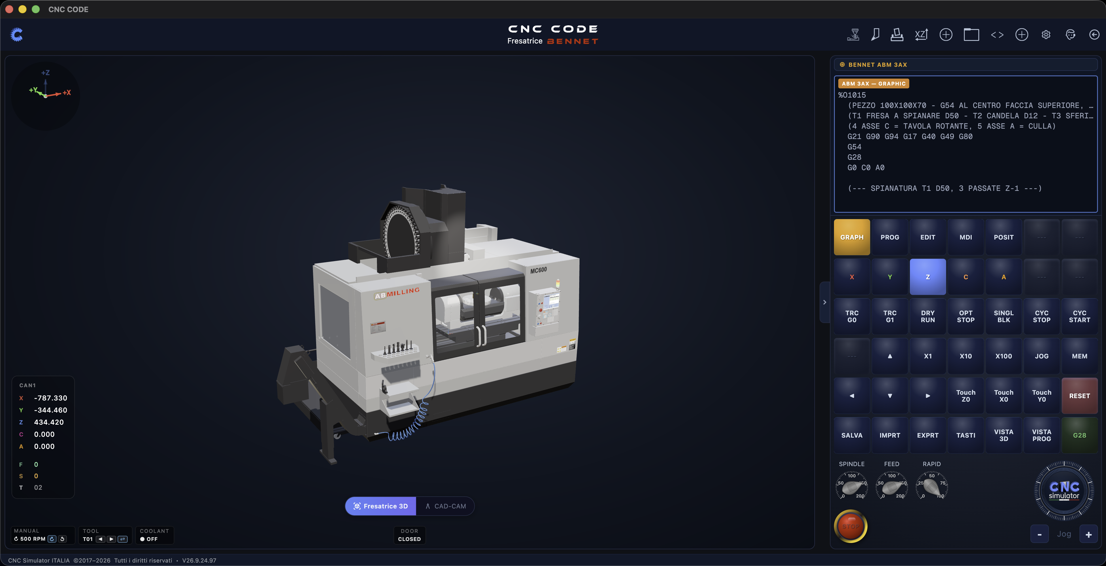
Unlike the lathe example in the previous chapter—which had a dual-channel design— this milling machine has a single channel: This is the most common case. The overall layout remains the same: 3D viewer in the center, position indicators at the bottom left, editor and command keyboard on the right, and toolbar at the top.
8.2 Machine Position and Status Indicators
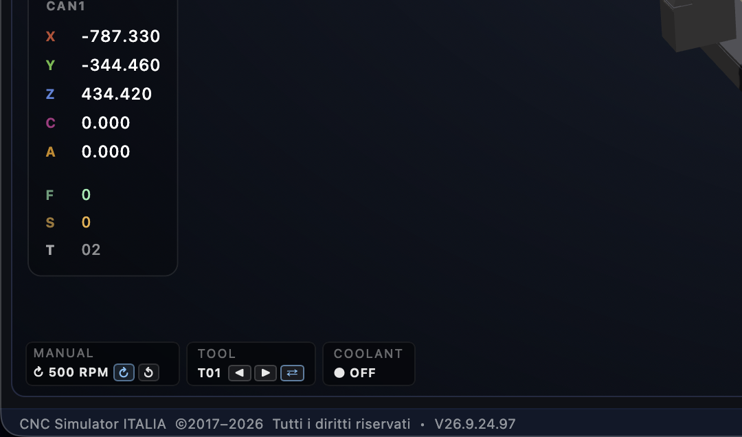
The axes shown are X, Y, Z, plus—when the machine has them—
C and A—not just generic “extra axes,” but
actual rotary axes: in the sample program for this machine, a comment makes this
explicitly clear: 4 ASSE C = TAVOLA ROTANTE, 5 ASSE A = CULLA. Below the
coordinates, the status bar is simpler than that of the lathe: no
turret or jaws, because they don’t exist on a milling machine—instead, you’ll find
TOOL, with arrows to scroll through the tools in the tool magazine and
change the active tool directly from here.
8.3 The Command Keyboard — What's Different from the Lathe
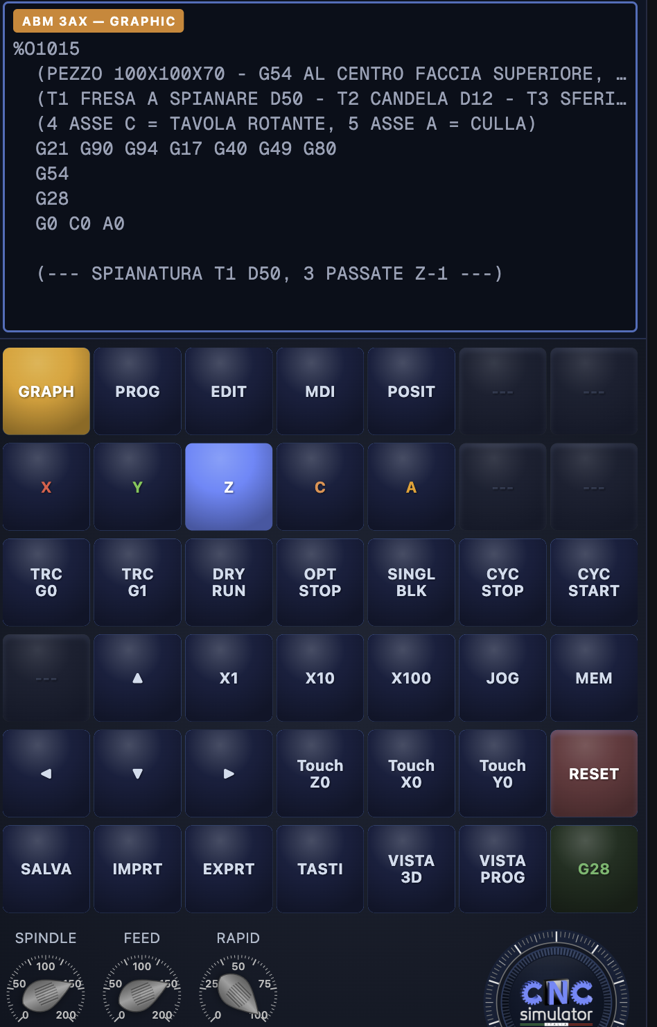
The structure is the same as that shown in Chapter 7.5—GRAPH,PROG,EDIT,MDI, and POSIT views, axes, single block, jog, touch-off, and override—with the following differences:
| Entry | Lathe | Milling Machine |
|---|---|---|
| Available Axes | X, Z, Y, C, B, A, W (second channel) | X, Y, Z, and C/A only if the machine has rotary axes |
| CAN1 / CAN2 | Available on dual-channel machines | Not included — the milling machines in the catalog are single-channel |
| Button after TRC G1 | CUT — Enables 3D chip removal | DRY RUN — runs the program without material removal, for a dry run |
| The last button on the SAVE row | ZERO RET — machine reset to zero | G28 — same function, called using the direct code |
8.4 The Toolbar — Two More Icons

The first ones, which are all shared with the lathe, are 3D Measurement, Manual, PrintPDFs, the Cutting Calculator, and Project Management. In addition, toward the center of the row, the milling machine has two icons that the lathe does not have: one with angle brackets <>—presumably the G/M Code list, the same function found in the Home menu—and a second button shaped like a +. Rounding out the row are Settings, Wizard, and the return to Home button, just like on the lathe.
Practical Example — A Pin with a Chamfer and Step (LATHE)
Theory is useful, but you learn to use a lathe by actually running it. In this chapter, we’ll work together on a real workpiece, from start to finish: a blank bar that becomes a pin with two diameters, featuring an entry chamfer and a clean step. We’ll do everything a operator does at the machine: mount the blank in the jaws, set the workpiece to work zero, set up the turret and check the offsets, write the program, and run it— first block by block, then automatically. Here, if you make a mistake, you don’t risk damaging the tool.
9.1 Part Drawing
Let's start with a simple but complete drawing, with all the dimensions we need to write the program. In CNC Code, the drawing is created directly in the CAD/CAM software (Chapter 11): a pin with two diameters, featuring a sharp 90° step and a chamfer at the tip, dimensioned in 2D View and checked in 3D View.
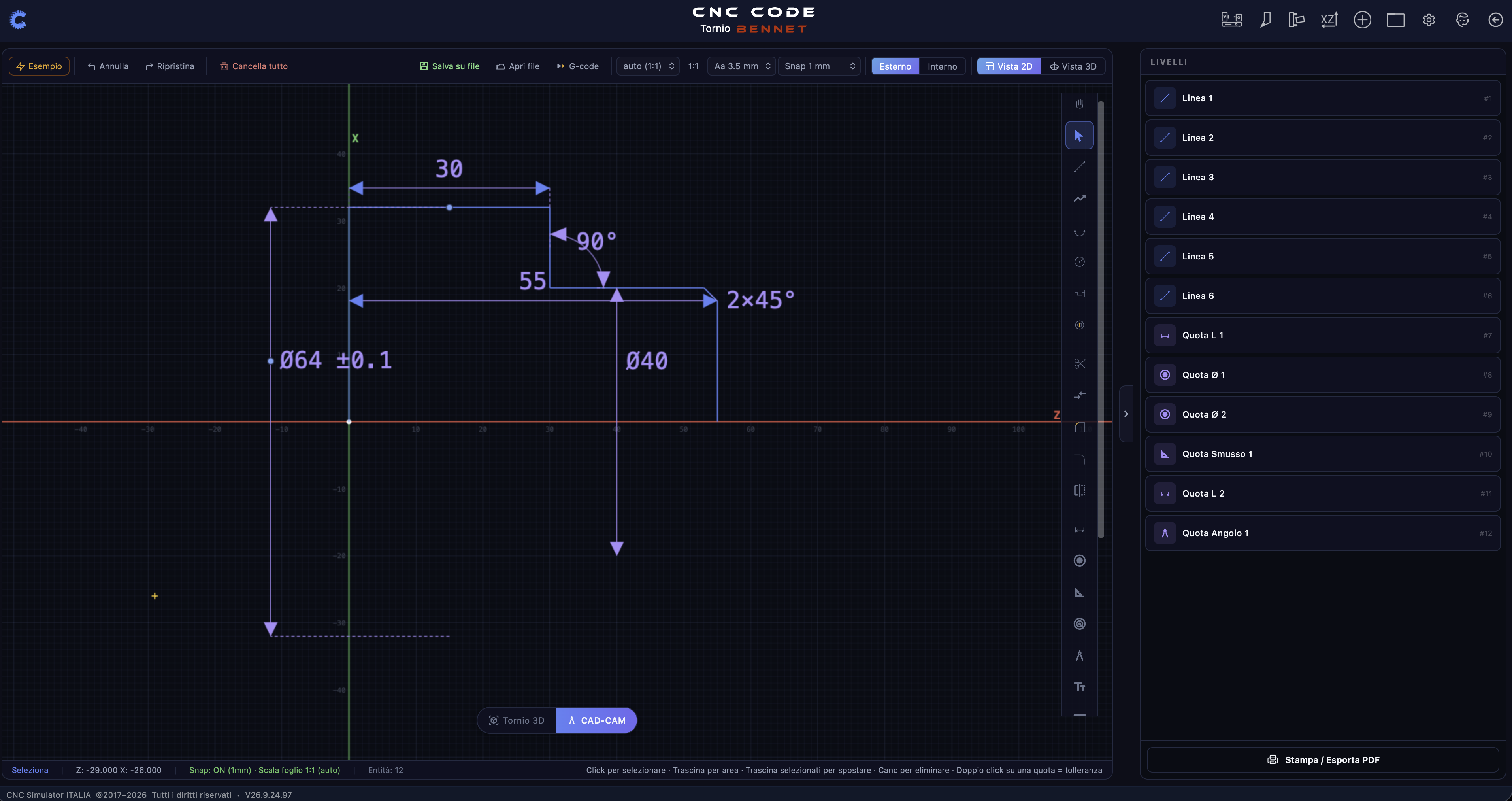
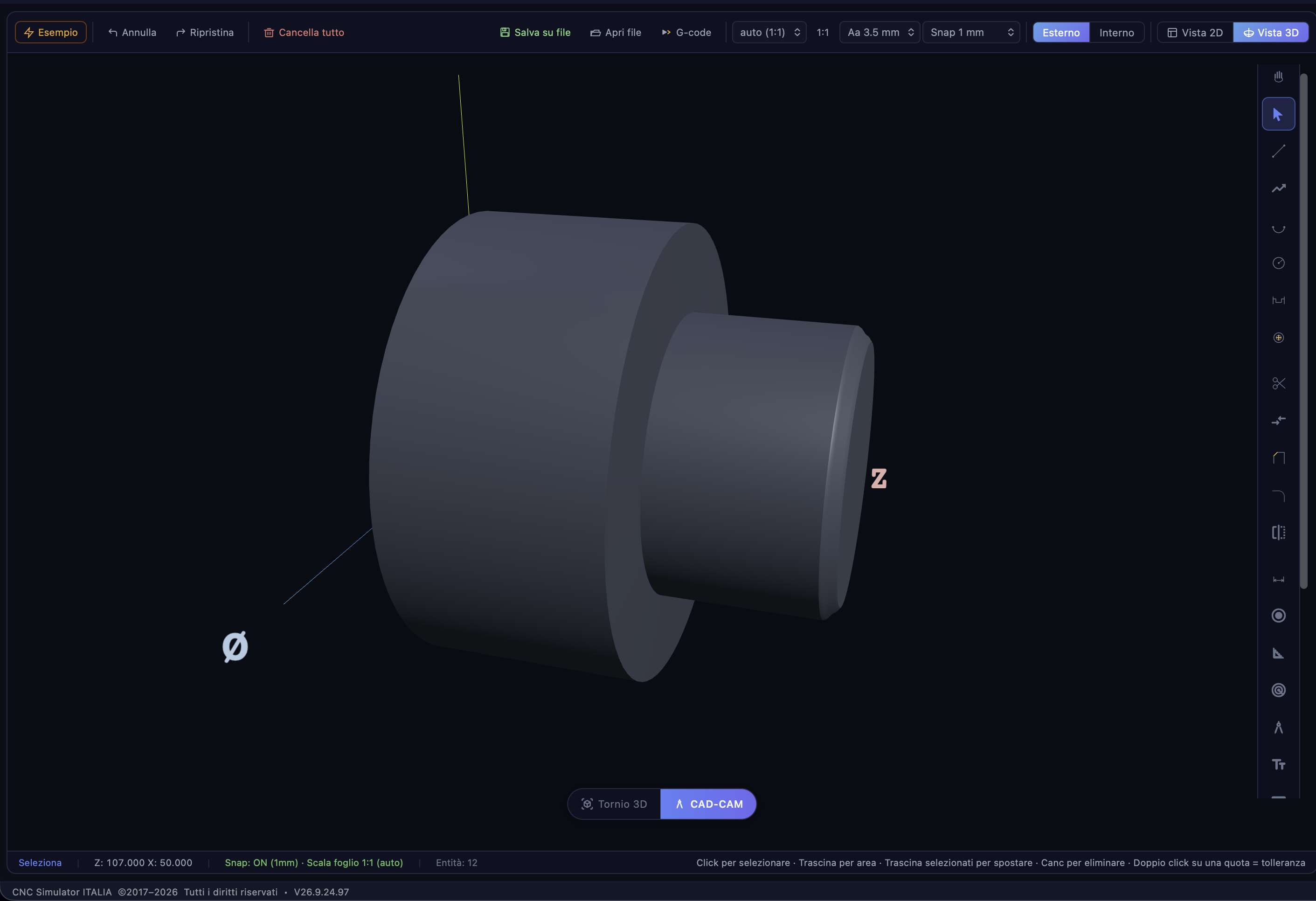
For this exercise, we will use the following dimensions:
| Element | Dimension |
|---|---|
| Starting Weight | Ø40 bar, steel: 25 mm clamped in the jaws and 61 mm protruding |
| Finished minor diameter | Ø20 mm, 25 mm length (exposed tip) |
| Entry Chamfer | 2 × 45° on the free end |
| Step | 90° straight shoulder from Ø20 to Ø32, 25 mm from the tip |
| Finished Major Diameter | Ø32 mm, 35 mm in length, up to 60 mm from the tip |
| Length of finished part | 60 mm: the extra millimeter on the blank is the stock allowance for facing |
| Work Zero (G54) | Z0 at the end face of the pin, X0 on the spindle axis, X in diameter |
9.2 Start the Lathe and Mount the Blank
From the Home screen, move the carousel to the lathe slide and press Start (Chapter 6): the simulator opens with that machine, ready to go. On the left is the 3D lathe; on the right is the CNC panel with the monitor and control keyboard (Chapter 7). In the upper right corner are the menu items we’ll use in this exercise:
| Menu item | What is the purpose of this exercise? |
|---|---|
| Spindles and Workpieces | jaws, blank, material, tailstock, or sub-spindle |
| Part Origins (G54-G59) | the origins and, in the second tab, the tool correction table |
| Tools | equip the turret stations |
| My Projects | Saved programs and projects |
| Home Lathe | closes any panel and returns to the CNC keyboard |
Open "Spindles and Workpieces." The right-hand panel shows the orange APPLY button at the top and, below it, two groups of tabs. In the first group, "Spindle Diameter" serves as a guide: enter the diameter of the workpiece (40), and the "Recommended Spindle" drop-down menu will show you the sizes with a green checkmark and the message “Spindle … suitable for the workpiece,” along with the grip range (min. Ø to max. Ø). This is just a check; it doesn’t set anything up. The actual work is done in the second group of tabs.
Options Tab: Select NONE (no tailstock or sub-spindle; the workpiece is short and cantilevered). Jaws Tab: select Jaws and the 3-Step Kit, then Select this kit. Workpiece Tab, WORKPIECE PARAMETERS section: Workpiece → Solid, Clamping Length (L2) 25, Length (L3) 61, Diameter 40, Material → Steel. L2 is how much of the blank is inside the jaws, L3 how much protrudes: the simulator loads a bar with a length of L2 + L3 and clamps it by its diameter.
Click "Add Workpiece" (the green button at the bottom of the tab, which does the same thing as "APPLY" at the top). In the 3D view, the bar appears in the jaws; the jaws close around the Ø40, and the confirmation “Tool loaded” appears at the bottom with the workpiece summary and the active origin, Offset: G54. If you’re not satisfied with the stick-out, the “Grip Ø” and “Z Position” stepper controls let you adjust it in real time in the 3D view. “Remove Workpiece” only disassembles the bar: the jaws opening remains stored for the next blank.
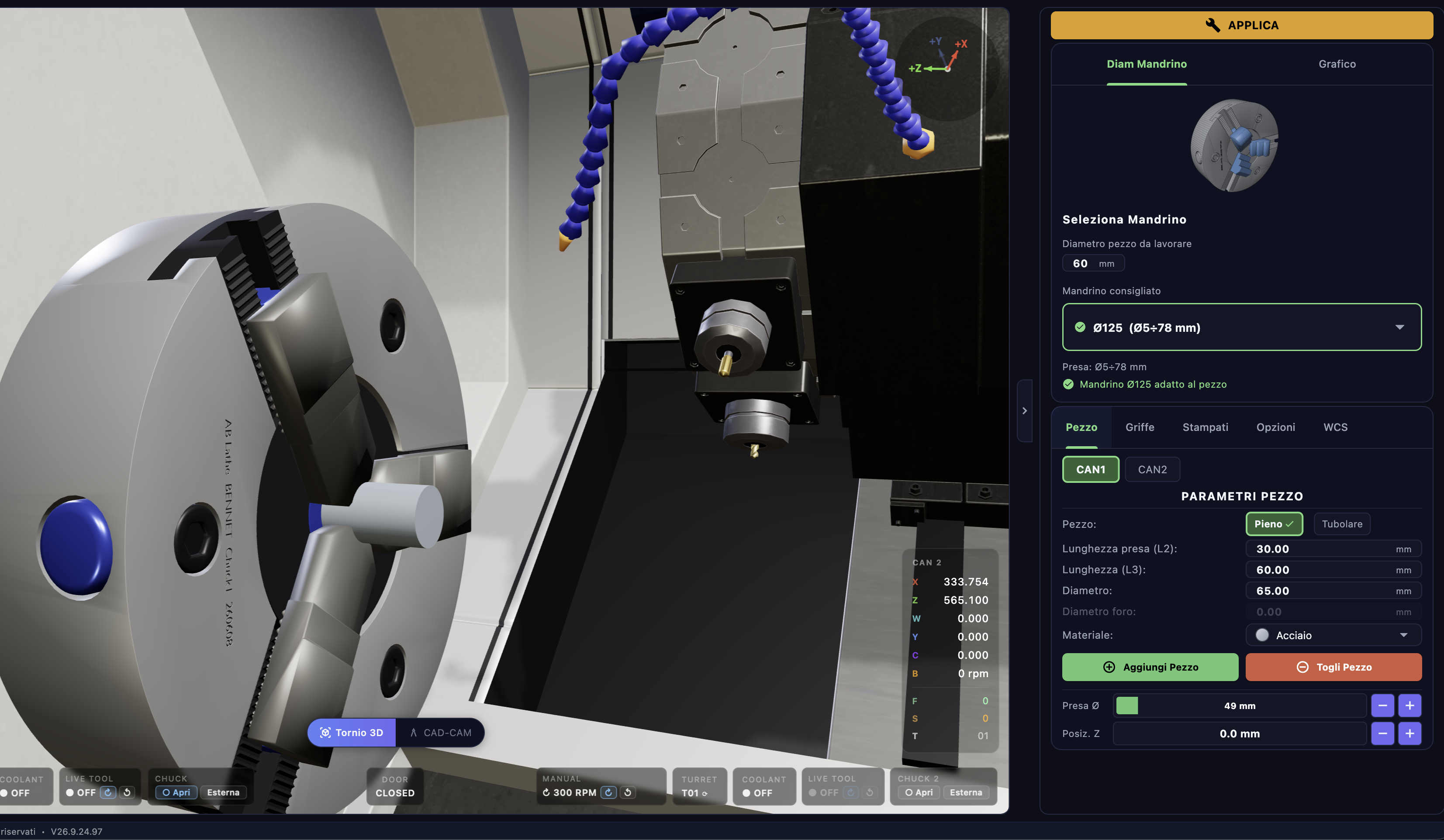
9.3 The Work Zero — G54
On the lathe, the workpiece zero has two axes. X0 is always the spindle axis: it isn’t set—it’s determined by the machine itself—and every X in the program is a diameter measured around that axis. You decide Z0, and the shop rule is to set it on the finished face of the workpiece, so that all lengths in the drawing are read directly as negative Z values. The link between the workpiece zero and the machine’s zero point (which in the simulator is the spindle face) is the G54 origin.
The simulator gives you a hand: when you've pressed Add Workpiece, the zero Z of the active origin has been set on the exposed side of the blank, and as long as you don't touch it, it stays there. You can check this by opening Part Origins (G54-G59): the fact sheet Origins show the line Assets: with chips MCS · G54 · G55 … G59 (MCS is not an origin; it is simply the way coordinates are read in machine coordinates) and the offset table with the columns G | X | Y | Z. In line G54, Z represents the distance between the spindle face and the free end of the bar, that is, its stick-out. The values can be corrected manually in the cell, and the ✕ at the end of the line resets it to zero.
Checking the zero point as in a machine shop — using the facing allowance
The blank protrudes 61 mm, but the finished pin is 60 mm long: that one millimeter is removed by machining, so the zero mark does not go on the rough side but 1 mm further in. This is the action performed by a real operator, and in the simulator, it is done from the CNC panel. Activate JOG, select the axis Z and the resolution (X1 · X10 · X100) and bring the tip of the tool to lightly touch the surface of the workpiece with the handwheel, using the buttons − / + or using the arrow keys on the computer keyboard (◀ ▶ move the Z axis, ▲ ▼ move the X axis, in 1-mm increments, or 10 mm with Shift). The box CAN 1 At the bottom left of the 3D view it shows you the tip in part coordinates: when the Z value is 0.000, you're on the face.
Press Touch Z0. The "Touch Z - Work Zero · CAN 1" window opens: "The touched point becomes this workpiece Z dimension." In the Workpiece Z (mm) field, enter 1 and confirm: the rough face is now at Z+1, and the Z0 in the program is exactly where the finished face will be. The screen confirms “Workpiece Zero Z set: Z… (G54).” The “Unmachined Face = Z0” button in the same window does the opposite: it resets the zero to the current unmachined face without touching anything—useful after facing, when the actual face has shifted.
To determine your current position, the monitor’s POSIT view has two blocks: ABSOLUTE (the tip in workpiece coordinates, X in diameter) and MACHINE (the carriage in machine coordinates, U/W, with X in radius and Z from the face of the jaws). With the zero point just set, the tip is on the blank face; ABSOLUTE shows Z 1.000.
9.4 Load the Turret and Reset the Tool
For an external profile requiring roughing and finishing, all you need is an external turning tool with an 80° or 55° rhomboid insert, nose radius 0.8, mounted in station T01. Open Tools: The panel lists all turret stations—T01, T02…, each with a thumbnail of the tool or the text “Empty slot—tap to add.” Click T01: the station editor opens for T01 — CAN1.
The setup follows the order of the actual machine. TOOL HOLDER section: Select "Front External" and press "Mount this tool holder." TOOL section: the carousel shows only the tools compatible with that holder; scroll to the external turning tool and click “Select this tool.” Adjust the stick-out using the slider and set the radius INSERT RADIUS (r) to 0.8. Finally, at the top, APPLY TOOL: in the 3D view, the turret shows the tool mounted in T01. If you ever change just one parameter and reapply the same tool to the same holder, the settings will remain the same.
The correctors: X, Z, TIP, R
Each station has its own offsets, which the program retrieves using the last two digits of T. This information is located in Workpiece Origins (G54-G59) → Tool Offsets tab, columns T | X | Y | Z | TIP | R: X is the radial deviation of the tip, Z is the longitudinal deviation, TIP is the cutting edge quadrant according to the convention Fanuc (0-9), and R is the nose radius used for compensation. On an actual machine, you determine these numbers yourself, tool by tool, using the presetter or by lightly touching the workpiece: this is the zeroing process.
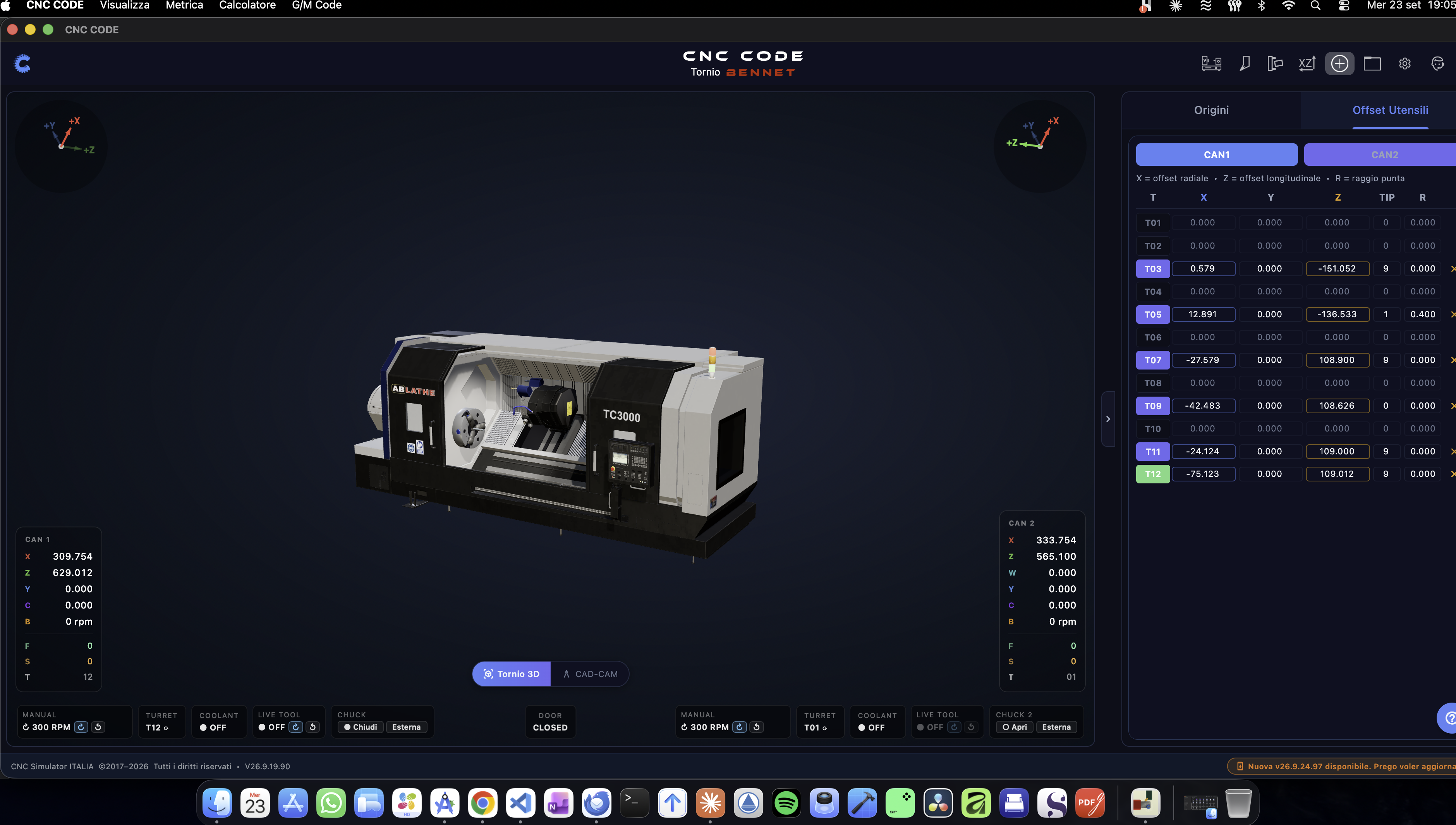
In the simulator, the initial zeroing is already done: the 3D lathe automatically measures the geometry of each mounted station, so at the first T0101, the cutting edge is exactly where it needs to be. The Touch operations remain the same as in the workshop: corrections. To replicate the actual operation, with “JOG” enabled, bring the cutting edge to just graze the diameter of the blank (Ø40, which you know) and press Touch X0: “Touch X - Presetting” opens, “Enter the diameter of the workpiece you are probing,” with the line “Writes the X offset for CAN 1 · T01.” Enter 40 and confirm: the X offset for T01 is calculated based on the carriage position and saved in the table, with the message "T01 — X offset set: Ø40.0".
T0101
) has 4 digits: the first two indicate the
turret station
, and the last two indicate the correction register
to use—almost always the same number for both. The simulator won’t stop you if an
offset is incorrect: just like on the shop floor, you’ll notice it from the workpiece… or from a
collision alarm with the jaws.
9.5 Writing the Program
Press "EDIT" on the monitor: on the desktop, type directly using the computer's keyboard (Enter creates a new line), or use the KEYS to open the on-screen CNC keyboard. We'll build it in four steps: facing, roughing with G71, finishing with G70, and program termination.
Phase 1 — Facing
First, let's clean up the surface of the blank: the millimeter of allowance is removed, and Z0 becomes the actual surface:
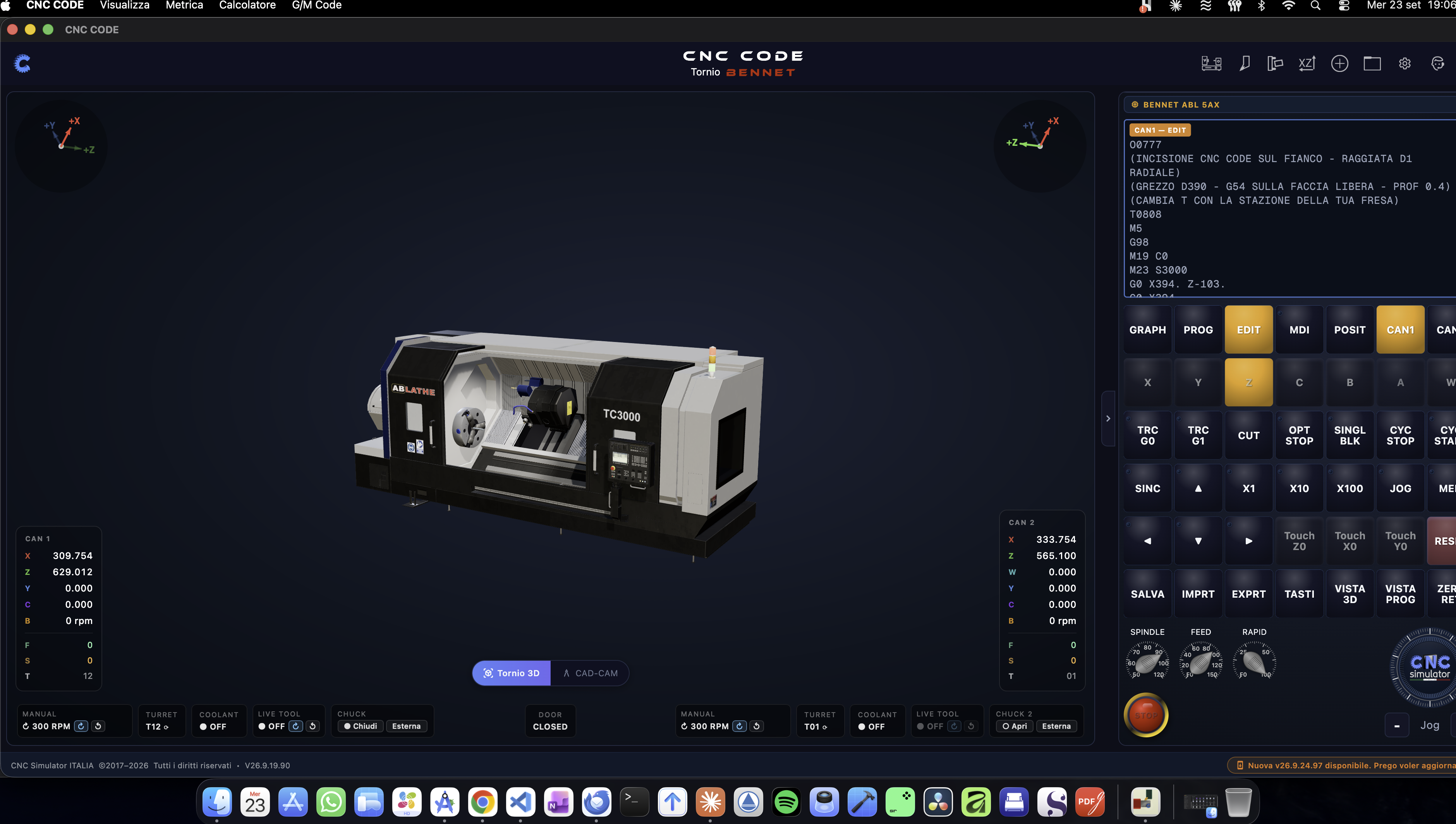
O0001
(PERNO CON SMUSSO E SCALINO)
(GREZZO BARRA D40 - Z0 SULLA FACCIA FINITA)
G21 G99 G97 G40
G50 S3000
G28 U0 W0
T0101
G96 S180 M03
G00 X42. Z2.
G01 Z0 F0.2
X-1.5 F0.15
G00 Z5.
X42.
G21 mm, G99 feed per revolution, G97 constant speed, G40 no compensation active. G50 S3000 limits the spindle to 3000 rpm for safety. T0101 indexes the turret to station 1 and activates its offset. G96 S180 M03 activates a constant cutting speed of 180 m/min in a clockwise direction. The G01 X-1.5 block machines just past the center to avoid leaving a dimple in the center of the workpiece.
Step 2 — Roughing with G71
Now for the heart of the program: the G71 cycle removes all excess material in repeated passes, following the profile we specify between sequences N10 and N20:
G71 U2. R0.5
G71 P10 Q20 U0.3 W0.1 F0.15
N10 G00 X16.
G01 Z0 F0.1
X20. Z-2.
Z-25.
X32.
G01 Z-60.
N20 X40.
Line by line: G71 U2. R0.5 — each roughing pass removes 2 mm from the radius, with a 0.5 mm retraction at the end of the pass. G71 P10 Q20 U0.3 W0.1 F0.15 — the finished profile is defined between sequences N10 and N20, with 0.3 mm of radial allowance and 0.1 mm of axial allowance left for finishing, feed rate 0.15 mm/revolution. Then the actual profile: from X16 (starting point, below the chamfer diameter), we move up with the 2×45° chamfer up to X20 Z-2, continue straight to Z-25 (end of the short section), sharp step down to X32, and straight to Z-60 (end of the workpiece, one millimeter from the jaws). The last line, beyond the diameter of the blank, is simply the safe exit point of the cycle.
Step 3 — Finishing with G70
After roughing, the G70 cycle re-machines the same profile (the N10-N20 sequences from earlier) at finishing speed, leaving the exact dimension specified in the drawing:
G70 P10 Q20Phase 4 — Program Closure
G00 X100. Z100.
M05
M09
M30
Rapid retraction to a safe position, spindle stopped, coolant shut off, end of program with rewinding — ready for the next part. Press SAVE: you can save just the program or the entire project, which includes tools, workpiece, and origins (Chapter 14).
9.6 Load into Memory and Execute
First of all, the jaws: The workpiece has been engaged ever since you installed it, but if you've opened them (button Chuck → ○ Open in the manual commands column below 3D, or M11 in MDI) close them with ● Close o M10: If the jaws are open, the CYC START command is rejected with the alarm "Jaws open - Close the jaws before starting the cycle." Then press MEM to load the editor program into memory, and GRAPH to view the machining operations in 3D.
First, block by block
The lathe does not have an "idle cycle": testing is done in steps. Activate SINGL BLK (one block for each press of CYC START), turn on TRC G0 and TRC G1 to view the rapid traverse path (amber dashed line) and the cutting path (solid green) in 3D, and set the FEED potentiometer to 20–40%. Press CYC START one line at a time and check in the “CAN” 1 pane that the tool moves to where you specified: X42 Z2 in front of the face, then the facing, then the G71 passes that descend 2 mm along the radius one after the other. CUT shows you a cross-section of the workpiece, so you can check the profile from the inside.
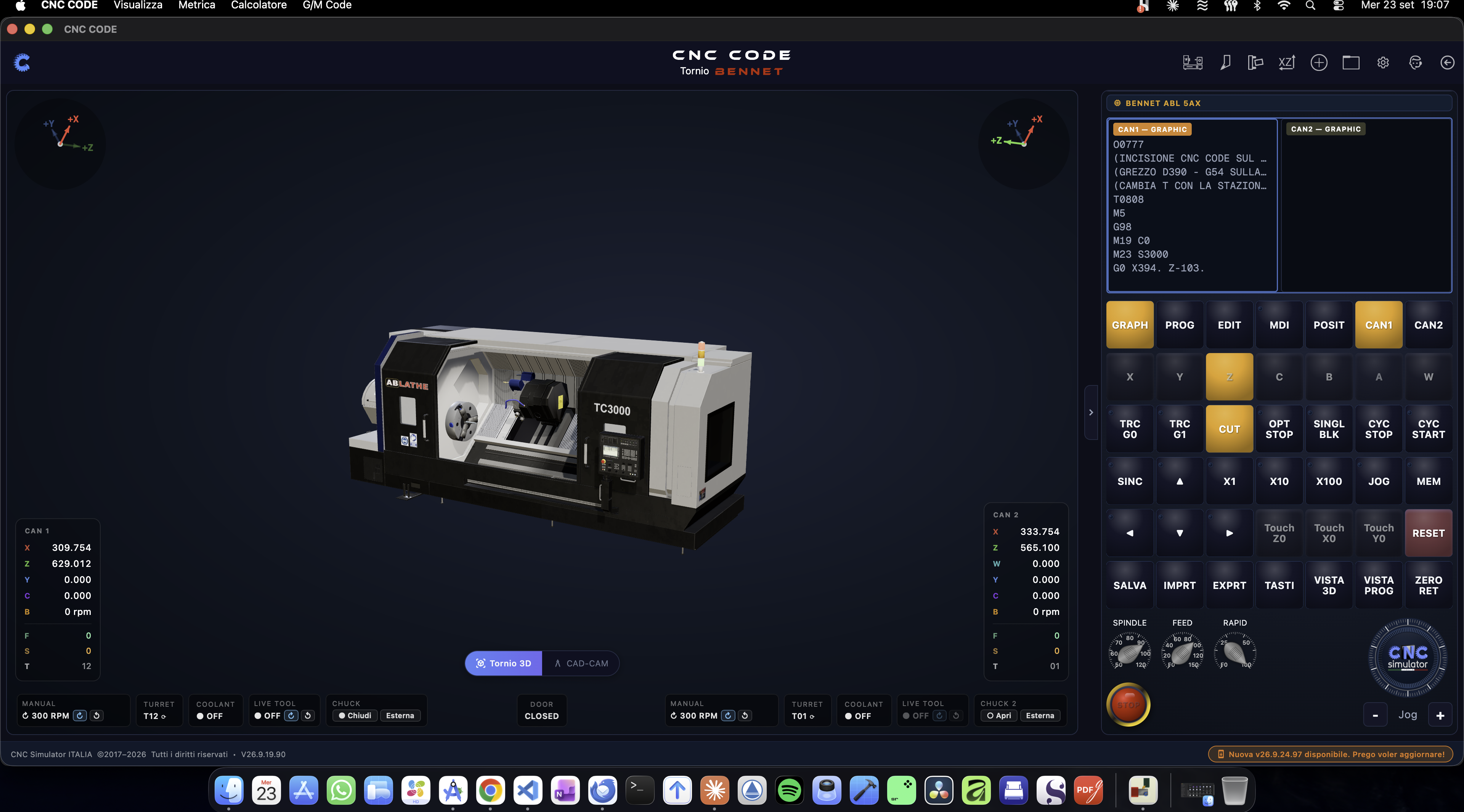
Then automatically
If everything checks out, press “RESET” twice within ten seconds (the second press restores the original blank: “RESET” ×2), clear SINGL BLK, set FEED back to 100%, then press “MEM” and “CYC START” again: the button turns green and the cycle runs automatically. During the cycle, you have the workshop controls: CYC STOP stops the axes in feed hold (CYC START resumes), the SPINDLE / FEED / RAPID potentiometers, OPT STOP to stop at the M01 points, and the red emergency stop button that puts the machine into emergency mode. In the “PROG” view, the currently executing line is highlighted in green; use the ▲ ▼ arrows to choose which block to restart from with CYC START.
9.7 Check the Workpiece and Start Again
At the end of the cycle, the view POSIT It provides you with coordinates, cycle time, and a piece counter. Press ZERO RET to return the turret to its home position (with the machine stopped and the tool away from the workpiece; otherwise, the simulator will reject it and notify you). Then 3D VIEW for full-screen mode and the 3D Measurement, from the menu Metric → 3D Measurement or by pressing M About 3D: Choose Diameter and click on the two cylindrical sections (Ø20 and Ø32), Distance between the face and the step (25 mm) and between the face and the end of the piece (60 mm), Corner on the bevel. Front view of the ZX (F) places the piece of profile, List of Measures collects them and Copy all It copies them to the clipboard. Esc closes the tool.
To repeat the exercise, you don't need to reassemble anything: pressing "RESET" twice returns the blank solid to the jaws; pressing it three times also resets the 3D view to its initial state; the origins and tools remain as you set them up. If, on the other hand, you change the blank from “Spindles” and “Workpieces,” remember that “Add Workpiece” resets the Z zero to the free face: repeat the “Touch Z0” with the allowance.
Practical Example — A Rectangular Step with a Center Hole (MILLING CUTTER)
Let’s move on to the milling machine. We’ll machine a blank plate by milling a rectangular perimeter step with tool radius compensation enabled, and drilling a center hole using a canned cycle. But before writing a single line of code, let’s do everything a real operator does: mount the blank, set the work zero, prepare the tools with their offsets, and only then run the program—first as a test run, then for real.
10.1 Part Drawing
The starting workpiece is a rectangular plate. In the center of the top surface, there is a rectangular island measuring 60 × 40 mm, which is 5 mm higher than the rest of the plate, which is lowered all around it (the perimeter step); in the center of the island is a Ø10 center hole, 10 mm deep.
| Element | Dimension |
|---|---|
| Starting Weight | plate 80 × 60 × 20 mm, brass |
| Island (perimeter step) | 60 × 40 mm, 5 mm high, centered on the blank: from X10 to X70, from Y10 to Y50 |
| Center hole | Ø10 mm, 10 mm deep, at the center of the island: X40 Y30 |
| Work Zero (G54) | front left edge of the top face: X0 Y0 at the corner, Z0 on the face |
10.2 Start the Milling Machine and Load the Blank
From the Home screen, navigate to the milling machine slide in the carousel and click Start (Chapter 6). The simulator opens with the machine ready: on the left is the 3D Milling Machine, and on the right is the panel with the monitor and control keyboard (Chapter 8). In the upper right corner are the icons for the work windows: hover your mouse over them to see the name of each one.
| Icon | What is the purpose of this exercise? |
|---|---|
| Vices and Workpieces | clamping on the workbench, blank, material, work zero, position on the workbench |
| Origins of the Workpiece | Check and, if necessary, probe the G54–G59 origins |
| Tools | the tool table with the H and D offsets |
| My Projects | Saved programs and ready-to-use examples |
| 3D Measurement | inspect the finished part |
Open “Vices and Workpieces.” The window opens in the right-hand panel and is divided into sections. In the first section, “CLAMPING ON THE WORKBENCH,” choose how the workpiece is held: for a plate, a mechanical vise is suitable. Next to the selection , the support height appears (60 mm for the vise): this is the dimension by which the base of the blank rests above the workbench, and the simulator uses it to position the workpiece at the correct height in 3D. If the vise has jaws, below that you also select the Jaw Grip, that is, how many millimeters of the blank fit inside the jaws and how many remain free.
In the workpiece section, set the blank: from the Blank (L × P × H) drop-down menu, select Custom…; this opens the blank window with the fields Width X, Depth Y, and Height Z in millimeters: enter 80, 60, and 20, then click Save Blank at the top. The notice states that saving the blank resets the simulation: that’s what we want—we’ll start from scratch. Back in “Morse and Workpieces,” select Material → Brass.
This is also where you'll make the most important decision in the entire exercise: Work zero (top or bottom). Choose Face · left front edge: From this point on, the simulator knows that X0 Y0 is the front-left corner and Z0 is the top face of the blank, exactly as shown in the drawing. Finally Seating Arrangement: awards Center it on the counter (o Center on the table if the machine has a rotary table). The summary row at the bottom of the section shows you everything at a glance: how many millimeters the workpiece is from the table, the dimension of the top surface, zero on the top surface, and the values that the simulator automatically entered in the G54.
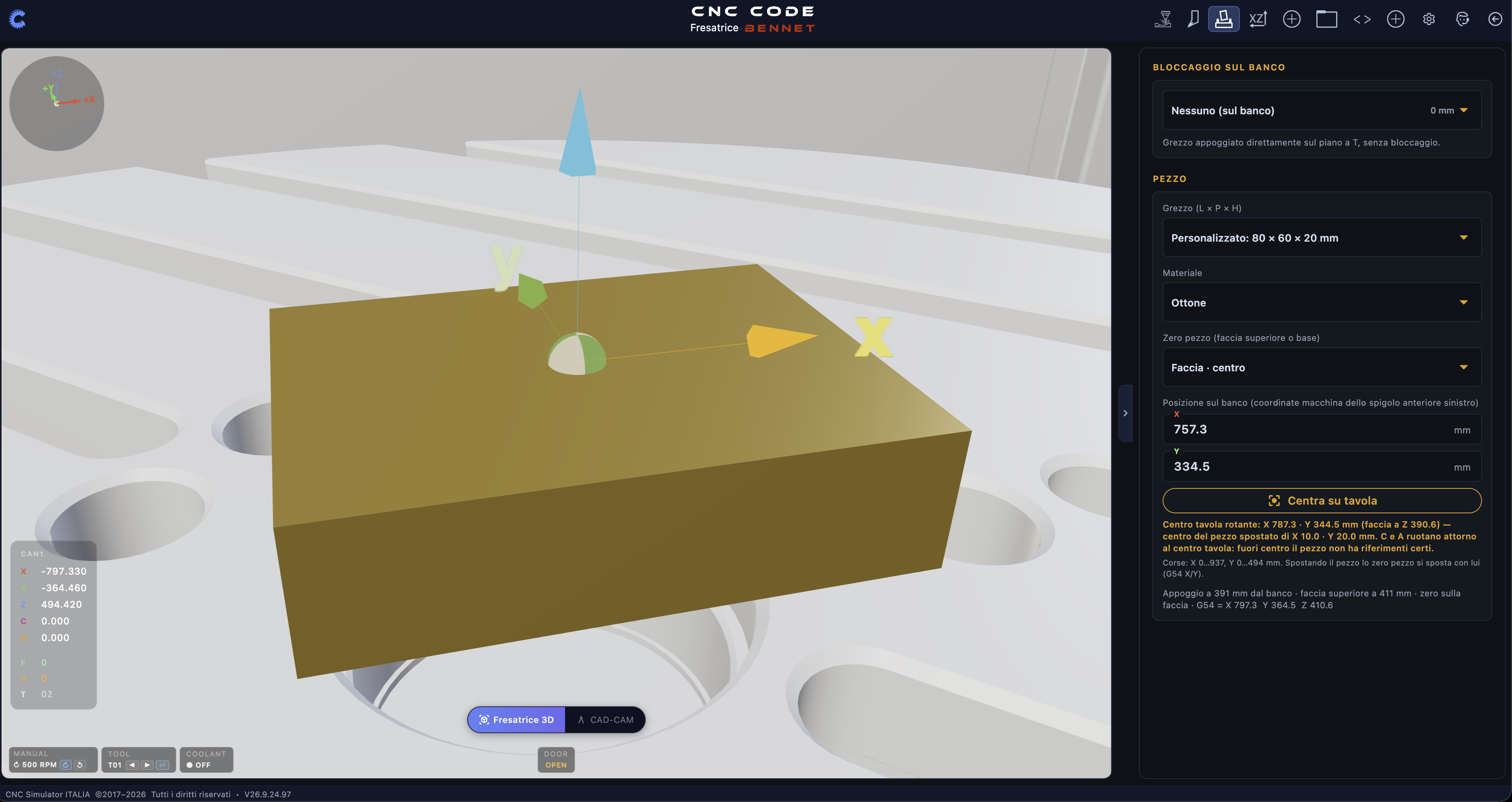
10.3 The Origins Workpiece — G54
In the milling machine, work is performed in part coordinates: Each coordinate in the program is measured from the part zero, not from the machine's zero point. The relationship between the two is theorigin active, which the program refers to as G54 (There are six of them, from G54 to G59, for machining six different parts or six different part numbers without rewriting the program.) The value of each origin is the deviation from zero machine: How many millimeters in the X, Y, and Z directions are there between the machine zero and the zero point of your part?
Open "Part Origins." At the top are the six fields G54 … G59; the active one is marked "active." Below that are the three fields X, Y, Z: if you followed step 10.2 as described, you’ll already find the values entered by the simulator—check that Z matches the dimension of the face (support + blank height, 60 + 20 = 80 mm with the mechanical vise) and that X and Y are those of the front left corner of the plate on the workbench. The buttons at the bottom are Set Active (makes the selected origin active), Apply (saves the manually entered values), and Reset to Zero.
Check the zero point as you would in a workshop
If you want to replicate the operator’s actual movements, the simulator allows you to do so. On the control keyboard, press JOG , select the axis using the X , Y , or Z keys, select the resolution using X1 / X10 / X100 (0.01 · 0.1 · 10 mm in increments) and move the tool using the handwheel or the − / + buttons until the tip just touches the top surface of the blank. At that point, press Touch Z0 : the current machine dimension is written to the Z axis of the active origin, and the monitor confirms "G54 Z set." Do the same for Touch X0 and Touch Y0 by bringing the tool close to the two sides of the front left corner. From this point on, the G54 is “yours”: the simulator stops realigning it on its own.
To see your current position at any given moment, the monitor’s POSIT view displays two blocks: ABSOLUTE, which shows the workpiece coordinates (axis minus active origin), and MACHINE, which shows the rough dimensions from the machine zero point. With zero properly set, and the tool resting on the corner of the blank, the ABSOLUTE line reads X0 Y0 Z0.
10.4 Prepare the Tools and Correctors
You'll need two tools for this workpiece:
| Station | Tool | Usage | Concealers |
|---|---|---|---|
| T1 | Cylindrical end mill, Ø12, 4 cutting edges | perimeter step | H1 (length), D1 (radius) |
| T2 | 10 mm tip, 120° point | center hole | H2 (length) |
Open Tools. The table lists stations T01, T02… up to the number of positions on the turret; next to each row, you can see where the tool is located (MAND = in the spindle, P nn = in cup nn) and its H and D offsets. Click the T01 row: the Edit Tool dialog box opens. Select the Type by scrolling through the photo carousel (End mill), enter a Description, then Diameter 12, Cutting edges 4, Length 50; you can leave the Shank Ø and Effective Length fields blank (the program calculates them automatically). Finally, enter the two offsets that the program will use: H Offset (length) and D Offset (radius). Click Save.
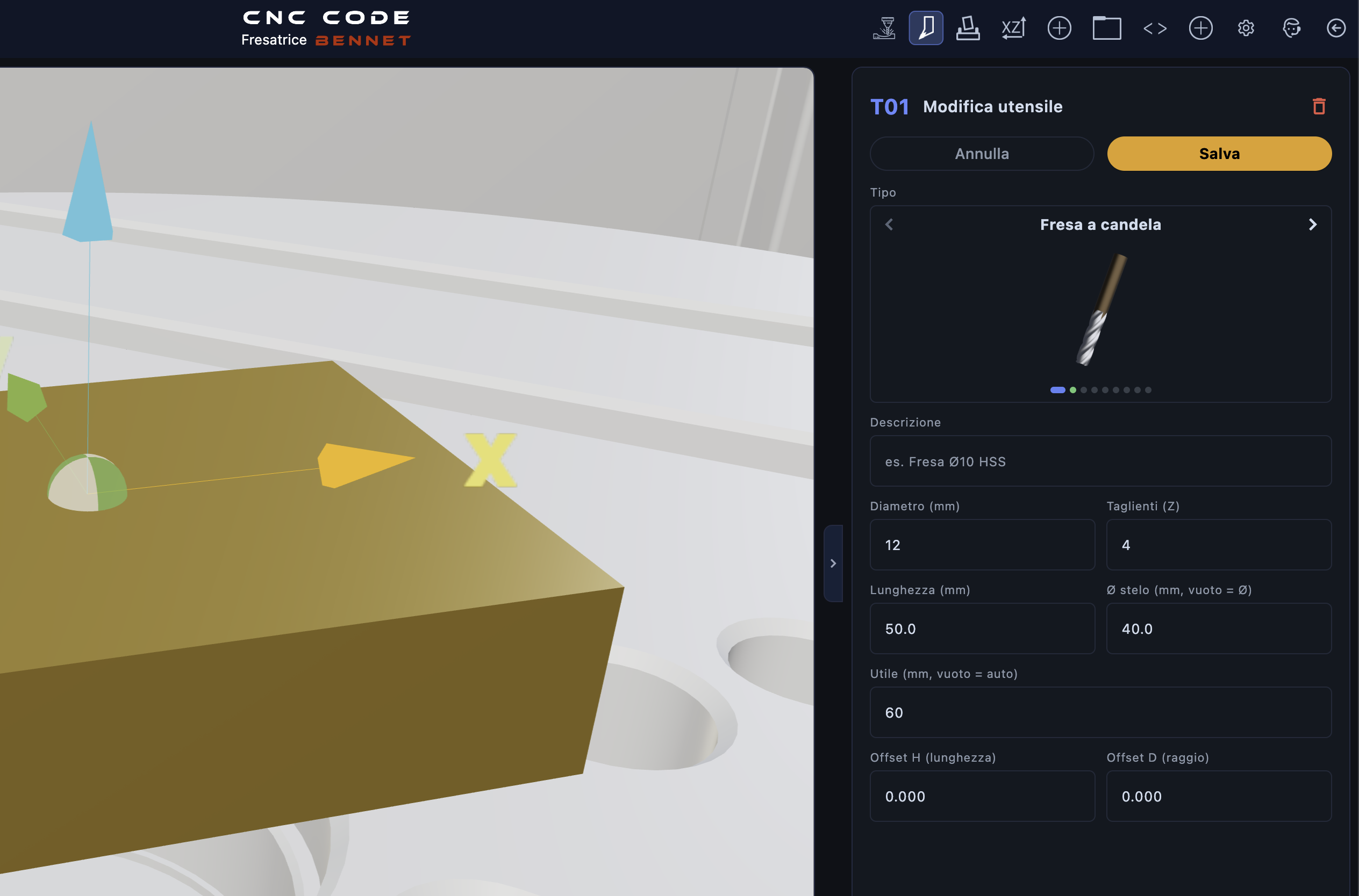
Repeat for T02: Type: Drill, Diameter 10, 2 cutting edges, Length 75, Point angle 120°, H Offset. Every tool that the program calls with a T must have its own row in the table: if it is missing, during the tool change the spindle remains empty, and on the first pass the simulator stops with the alarm “NO TOOL in the spindle.”
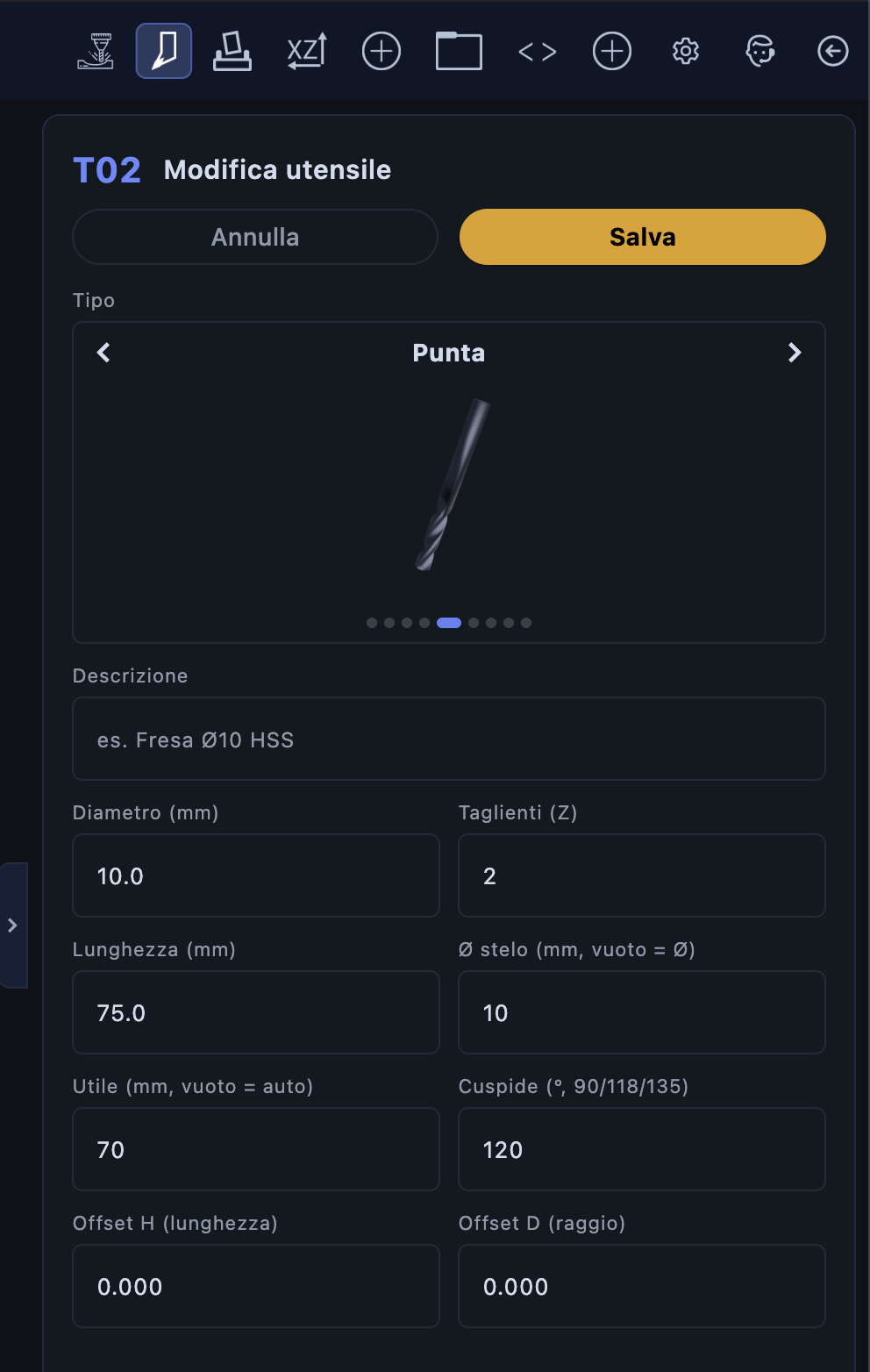
Resetting Tools: What Are H and D?
On a real machine, every tool has a different length, and before machining, it must be "zeroed": you measure how far its tip protrudes from a reference point (using the off-machine presetter or by probing the workpiece), and that number is stored in register H. When the program executes G43 H1, the controller shifts the Z zero by the amount stored in H1, so the tool tip actually goes to the programmed Z position. Register D, on the other hand, contains the radius of the milling cutter, which G41 D1 / G42 D1 use to keep the tool center offset from the drawn contour.
The simulator does not have a presetter or length probing : the H value is entered manually in the H Offset (length) field. In this exercise, with G54 Z set to the face of the workpiece and the tool lengths already known to the simulator, leave H = 0 for both: this means “no correction,” and the tip will go exactly to the programmed Z value. In the Offset D field of T01, enter 6 , the radius of the Ø12 end mill: this is the value that G41 D1 will use to offset the tool center from the contour. The simulator will tolerate it if you leave it at zero (in which case it uses the actual tool radius from the table), but on a real machine, an empty D field means no offset and a step that is 12 mm narrower: get used to entering it.
10.5 Writing the Program
Press EDIT on the monitor, then TASTI to open the app’s CNC keyboard: on the milling machine, you enter the program using that keyboard, key by key, just as you would on the control panel’s keyboard (EOB closes the block, INSERT inserts, ALTER replaces the word under the cursor, DELETE deletes). The program is divided into four stages.
Step 1 — Setting Up and Changing Tools
O0002
(GRADINO RETTANGOLARE + FORO CENTRO)
(GREZZO 80X60X20 - ZERO SPIGOLO ANT SX FACCIA)
G21 G17 G90 G94
G54
T1 M06
G43 H1 Z50.
S3000 M03
M08
G21 mm, G17 XY working plane, G90 absolute coordinates, G94 feed rate per minute. G54 activates the workpiece origin defined in 10.3. T1 M06 mounts the end mill: the Z axis rises to the tool-change dimension and the ATC arm changes the tool. G43 H1 Z50 activates length compensation with register 1 and positions the tip 50 mm above the face. Spindle at 3000 rpm, coolant on.
Step 2 — Milling the Step (with radius compensation)
G00 X-10. Y-10.
G00 Z5.
G01 Z-5. F80
G41 D1 G01 X10. Y10. F200
Y50.
X70.
Y10.
X10.
G40 G01 X-10. Y-10.
G00 Z50.
We position ourselves outside the workpiece (X-10 Y-10; the cutter is completely outside the plate), lower to Z-5 while still in open space, then G41 D1 activates the left-hand radius compensation as we enter the corner of the island: the controller shifts the center of the end mill by D1 = 6 mm to the left relative to the feed direction, i.e., always outside the island. The 60 × 40 rectangle (from X10 to X70, from Y10 to Y50) is machined counterclockwise; with the Ø12 end mill, the perimeter pass alone removes the entire 10-mm band around the island, all the way to the edge of the plate. G40 deactivates the compensation as we exit the workpiece.
Step 3 — Center Hole
T2 M06
G43 H2 Z50.
S2500 M03
G00 X40. Y30.
G99 G81 Z-10. R5. F100
G80
G00 Z50.
Tool change on the drill, using its length compensator G43 H2, positioning above the center of the island (X40 Y30), then the G81 drilling cycle: rapid feed to plane R (5 mm above the face), feed rate to the bottom of the hole at -10 mm, rapid return to plane R (G99). G80 cancels the cycle.
Phase 4 — Program Closure
M09
M05
G28
M30
Closed-loop coolant, spindle stopped; G28 alone returns the machine to the reference point (first Z up, then X and Y: never enter G28 Z0 in G90—with the zero on the face, Z0 is the workpiece) and end of program. Press SAVE and give the program a name: you’ll find it in My Projects → Saved (Chapter 14).
10.6 Load into Memory and Run
On the milling machine, the CYC START button starts the program only if you have saved it to memory: press "MEM," and the monitor will confirm "Program in memory" (if you forget to do this, the CYC START button will respond with "CYCLE START: press 'MEM' (program) or 'MDI'"). Then return to the “GRAPH” view to monitor the machining process in 3D.
First at a standstill
Just like on a real machine, the first pass is done without cutting. Enable DRY RUN (all movements at rapid feed rate, spindle and coolant off, blank stock intact), SINGL BLK (one block for each press of CYC START), and the two paths TRC G0 / TRC G1 , which draw the rapid traverse path (dashed line) and the cutting path (solid line) in 3D. Press CYC START block by block and watch where the tool goes: the trace should circle the island 6 mm from the outline and the tip should stop above the center. If something doesn’t look right, go to RESET , make corrections in EDIT , return to MEM , and start over.
Seriously, though
Turn off “DRY RUN ” and “SINGL BLK” and press “CYC START ”: the button turns green and the program runs automatically. You’ll see the step appear along the perimeter and then the hole open up in the center. During the cycle, you have the same controls as in the workshop: CYC STOP (feed hold: the axes stop; CYC START resumes from where you left off), the FEED and RAPID potentiometers to slow down, OPT STOP to stop at any M01 commands, and the red button that stops everything and puts the machine into emergency mode (as long as it is pressed, jog, touch, G28, and RESET remain disabled).
10.7 Check the Workpiece and Start Again
At the end of the cycle, the POSIT view displays the results: ABSOLUTE and MACHINE coordinates, WORKPIECE COUNT, cycle time, and total. To take measurements, press 3D VIEW (the 3D view takes up the entire screen), then open 3D Measurement from the top bar or with the M key: select Distance and click on the two sides of the island (it should be 60 and 40 mm), Depth between the face of the island and the bottom of the step (5 mm), and Diameter at the hole (10 mm). Esc closes the tool.
To restart the exercise from the beginning, you don't need to reassemble anything: press RESET twice within ten seconds, and the monitor will confirm "RESET ×2 — blank": the plate resets to full, and the origins and tools remain as you set them up. Do this three times, and even the 3D view will return to its initial state.
G41 and G40.
CAD/CAM for the TORNIO Lathe
Writing a profile by hand, line by line, is an excellent exercise (Chapter 9)—but for complex profiles, the lathe’s CAD/CAM software lets you draw the workpiece and generates the G-code for you. This is a “Premium” feature: if you don’t have an active license, the app takes you straight to the activation screen.
11.1 How to Open It
The lathe's CAD/CAM is not a separate screen: it is an alternative view of the work screen. At the bottom, next to the 3D Lathe button, you’ll find the CAD/CAM button—tap it to switch from the machine’s 3D viewer to the 2D drawing editor, on the same X/Z plane as the profile you’re working on.
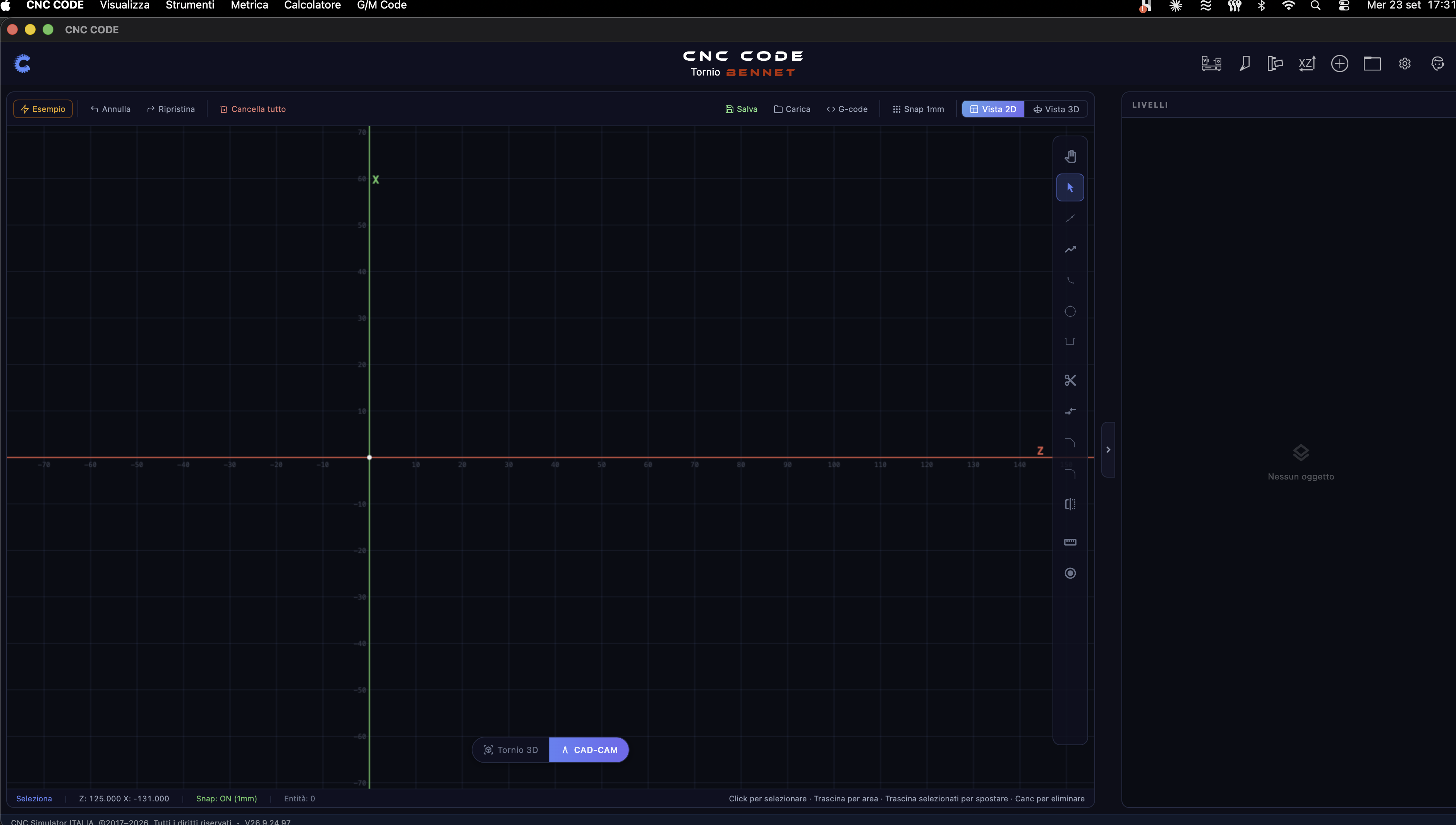
11.2 Drawing Tools
The top bar contains the project controls — Example (loads a demo profile, useful for immediately seeing the entire workflow), Undo/Redo, Clear All, Save/Load Drawing, the G-code button (see §11.3), Fixed-Step Snap (1 mm), and the toggle between 2D View and 3D View. The column of icons to the right of the canvas contains the actual drawing tools: hand (pan), selection, line, polyline, arc, circle, rectangle, as well as scissors (cut), fillet/chamfer, mirror, dimension, and a measurement ruler.
11.3 Draw (or Upload an Example) and Generate the G-code
Select a tool — for example Line — and the canvas confirms this in the lower-left corner: "Click p1 → click p2 (chain) · ESC to exit". Each subsequent click continues the chain from the last point, just as you would draw a line by hand on graph paper; press ESC to break the chain and start a new one. Each segment you draw appears immediately in the Layers panel.
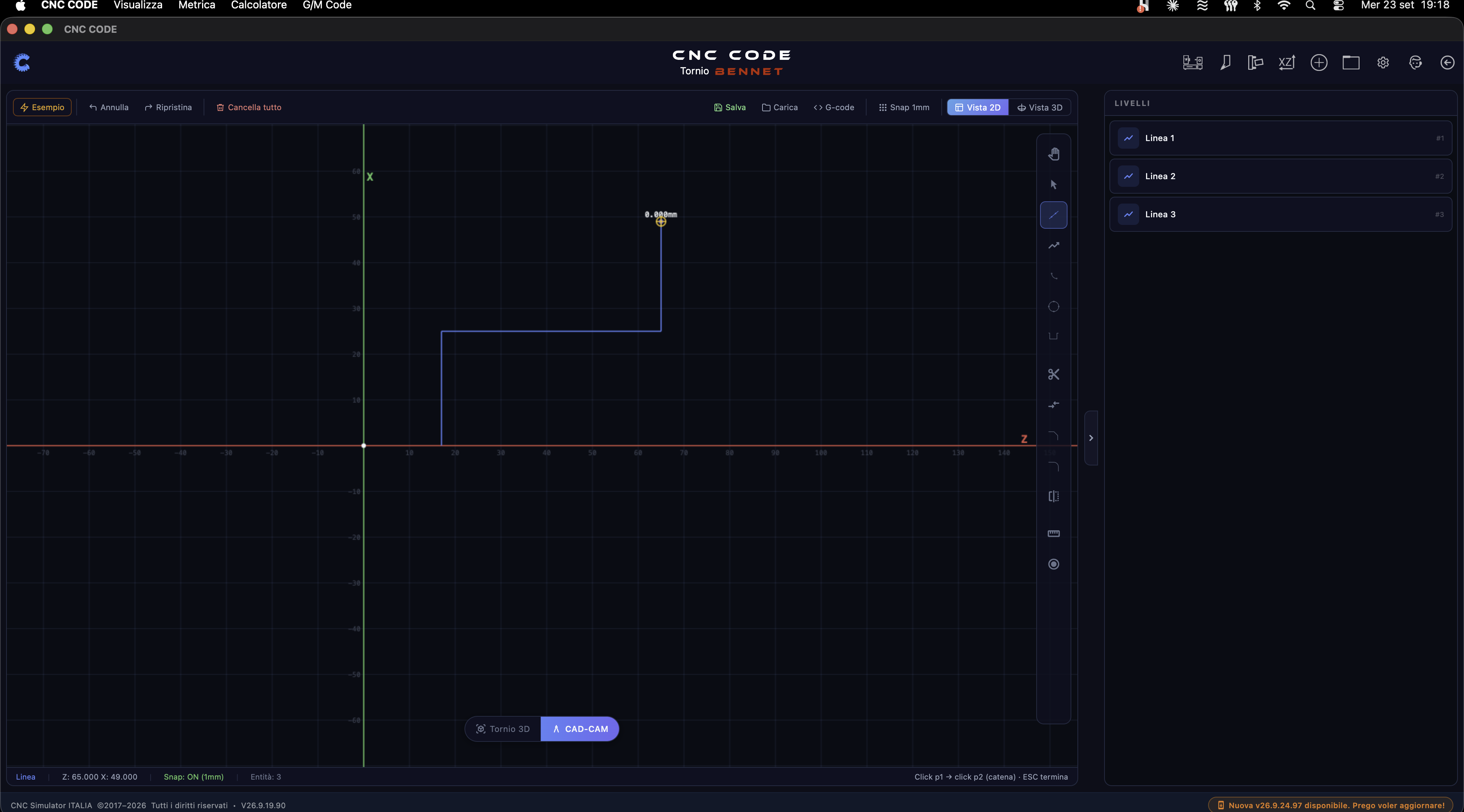
The quickest way to see the CAD/CAM interface already populated, without having to draw anything, is to click the "Example" button in the upper-left corner: it loads a complete demo profile, with each segment visible in the Layers panel.
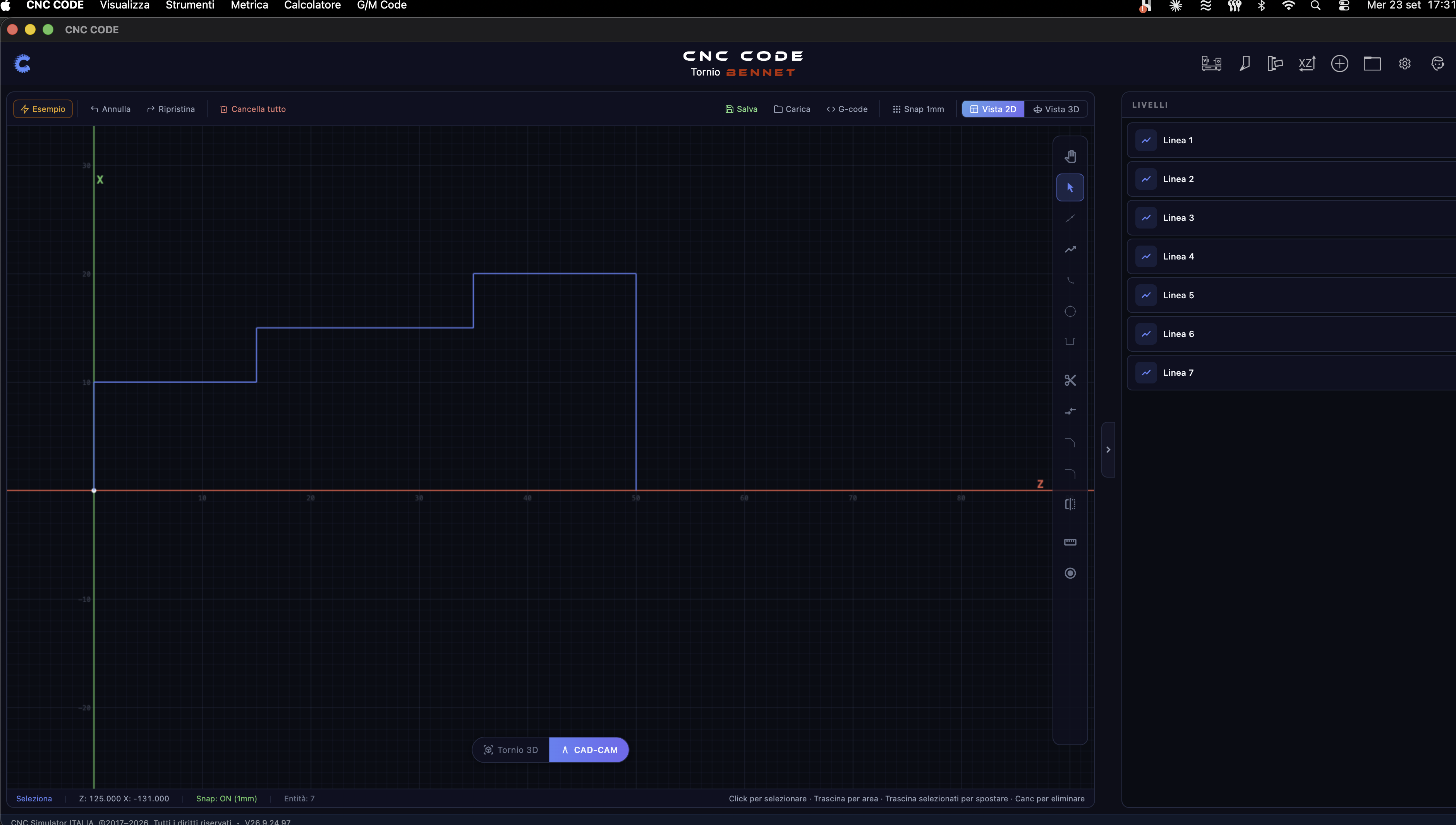
When the profile is ready, click "G-code" in the top bar: a window will open with the generated "Fanuc" program (header, unit, plane, tool, cutting speed, radius compensation) ready to be read.
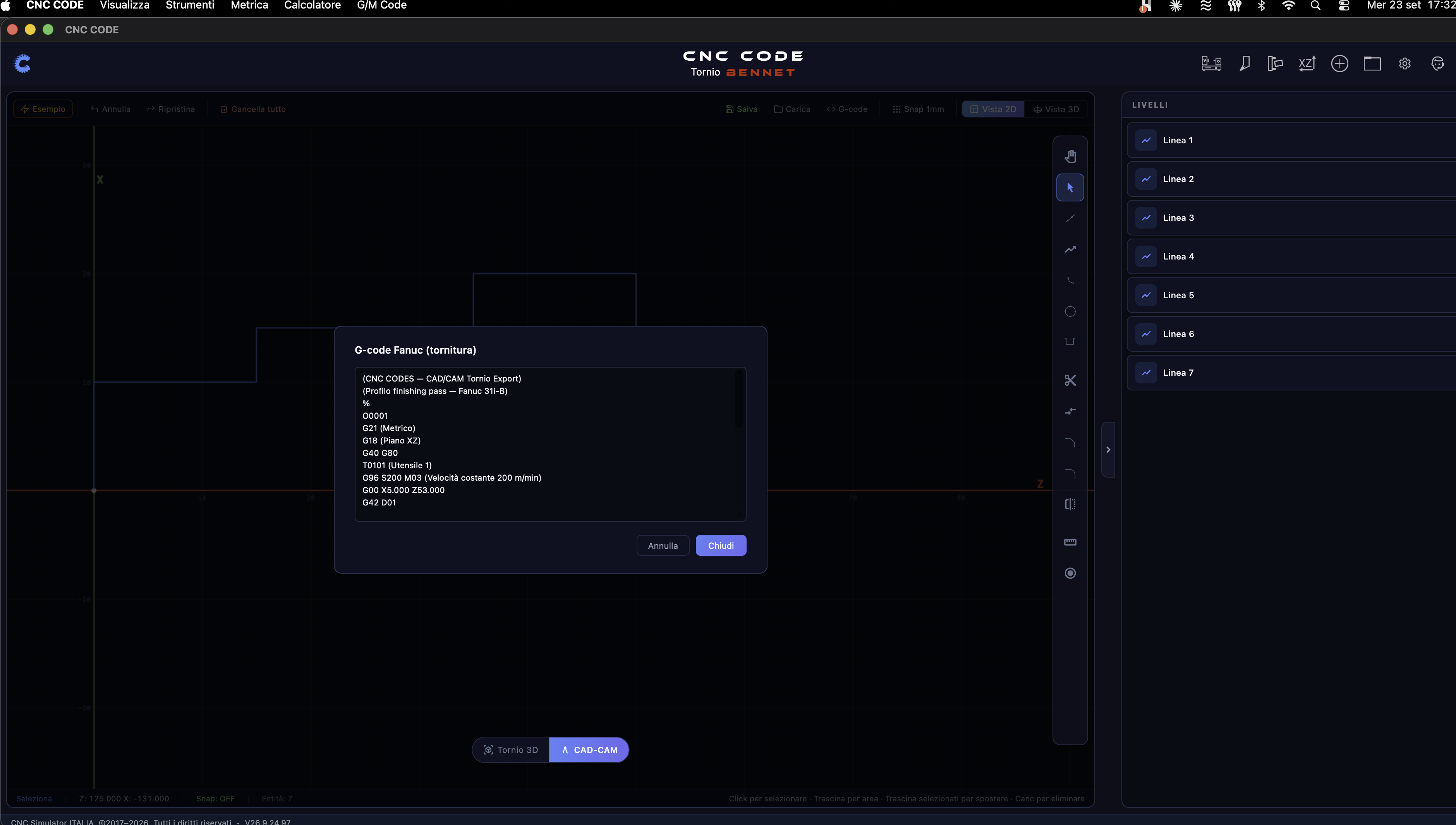
Ready-to-use sample files for each machine
If you want to try importing without having your own file on hand, CNC Code provides three workpieces for each machine, designed by us with round dimensions: for the lathe, three STEP (a shaft with a bearing seat, a bushing with grooves for Seeger rings, and a pin with radial holes and a countersunk hex), for the milling machine, three projects with the machining operations already set up (perforated plate, pocket with island, step, and facing), and for the 3D printer , three STL (L-bracket, vase, gear).
You can find them in two places. Within the app, via the Examples… button next to Import STEP in the Lathe Layers panel, next to Open DXF in the Milling Machine, and in the Printer Projects: the selected file follows exactly the same process as one of your own files. And on your hard drive, in the Documents/CNC Code/Examples folder, organized by machine: from there, you can also open them in your CAD software or import them using the standard Import button.
11.4 Title Block and Printing the Drawing
The CAD/CAM software also includes a title block editor—the panel containing the technical data of the drawing (company, date, scale)—and a print/export function that generates a dimensioned front view, with dashed centerlines and a filled out: perfect for printing or attaching the technical drawing of the workpiece, separately from the G-code program.
The button Print / Export PDF At the bottom of the Layers panel, it creates a compliant sheet ISO: layout with numbered areas, main view with dimensions, View A e View B (the two ends of the workpiece), Axonometric Projection 3D drawings, machining operations notes, general tolerances, revision table, and complete title block (draftsman, inspection, approval, material, heat treatment, customer, drawing number).
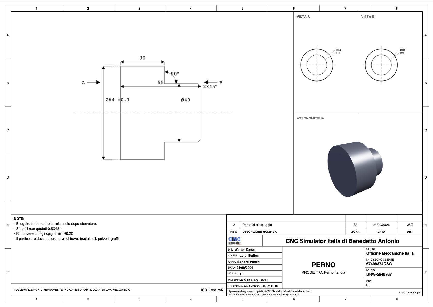
The CAD/CAM System for the FRESA Milling Machine
The milling machine’s CAD/CAM system shares the same philosophy as that of the lathe—it designs and then generates the G-code—but the workflow is different, because here the process is based on layer-by-layer operations, not on a single rotational profile. This, too, is a feature of Premium.
12.1 How to Open It
From the milling machine's work screen, the CAD/CAM menu item opens the full-screen editor, with the width, height, and depth of the current blank already set.
12.2 Drawing Tools
Compared to a lathe, chamfering, grooving, and threading are missing (these are rotational concepts and don't make sense on an XY plane), but on the other hand, you'll find shapes designed for milling:
12.3 Assign an Operation to Each Layer
Here, the milling machine goes beyond simply tracing the lathe’s profile: once you’ve drawn the geometry (perhaps on multiple layers—a rectangle for the step, a circle for a hole), open the G-code generation. First, select the target machine controller :
Then, for each layer of the drawing, you assign a machining operation (for example: this rectangle is a pocket, this circle is a hole)—it’s a true CAM approach, not just a contour path.
12.4 Preview, Copy, and Share
Once the program is generated, a preview window opens showing the number
of lines and the G-code in monospace font, which you can select. Just like on the lathe (Chapter 11), the
program does not automatically appear on the work screen: you have two
options, Copy (to the clipboard) or Share (saves a file
programma.nc and opens the system’s sharing window).
How "CNC Code" Tailors the Code to Your Needs
On an actual machine, the same workpiece may require G-code written differently depending on the control system—Fanuc, Siemens, Heidenhain, and Mazak use slightly different “dialects.” In technical jargon, the component that translates a program into the correct dialect is called a post-processor. In CNC Code, this step is automatic: you don’t have to configure anything, but it’s important to understand what’s happening behind the scenes.
13.1 No Buttons to Press
Unlike what you might expect from professional CAM software, in CNC Code there is no screen where you “generate” a post-processor . It’s not necessary: the program you write by hand (Chapters 9–10) or generate from CAD/CAM (Chapters 11–12) is automatically written in the correct dialect based on the machine and brand you selected from the Left Panel before launching the simulator.
13.2 What Changes from One Checkup to the Next
Here are some concrete examples of what changes automatically depending on the selected dialect (Fanuc and similar, Siemens, Heidenhain, Mazak):
| Element | What Might Change |
|---|---|
| Program Header | Program number using O and %, or in the style of Siemens, Heidenhain, or Mazatrol |
| Tool Change | T0101, or TX D1, TOOL CALL, TX M6, depending on the test |
| Spindle | Standard G96/G97 syntax, or "Siemens" style with "LIMS," or Heidenhain style |
| Drilling Cycles | G81/G83 or CYCLE81/83 (Siemens) or CYCL DEF (Heidenhain) |
| End of program | M30, M30 + %, M02, END PGM, M99 |
This "translation" occurs whether you write a program manually in the work screen, generate it from CAD/CAM (Chapters 10–11), or use the machine configuration wizard — always transparently, depending on the active brand.
13.3 Why It's Important to Know This
If you change the machine or brand in the Left Panel and reopen the same workpiece, the program you write from scratch might have a syntax slightly different from what you were used to—this isn’t a simulator error; it’s the same dialect you’d find when switching from a Fanuc to a Siemens in a workshop. This chapter is here precisely to help you understand where that difference comes from, before it seems like strange behavior on the app’s part.
Saving a Program
On the lathe, there are two ways to save your work, and the difference is important: a "light" save that saves only the code, and a "full" save that saves the entire workspace. Knowing which one to use will help you avoid unpleasant surprises when you reopen a project later on.
14.1 "Standard" or "Full" Program? — Lathe
| What do you save? | Contents |
|---|---|
| Program Only | The G-code for both channels (CAN1/CAN2, if present) — nothing else |
| Complete Project | Channel G-code + tool table (turret and rack) + blank geometry (diameter, length, tubular, material) + machine type (spindle/sliding headstock) + workpiece origins G54-G59 + units of measurement + tailstock type |
14.2 How to Save — Lathe
On the command bar of the work screen (Chapter 7), press SAVE. A dialog box opens with three options:
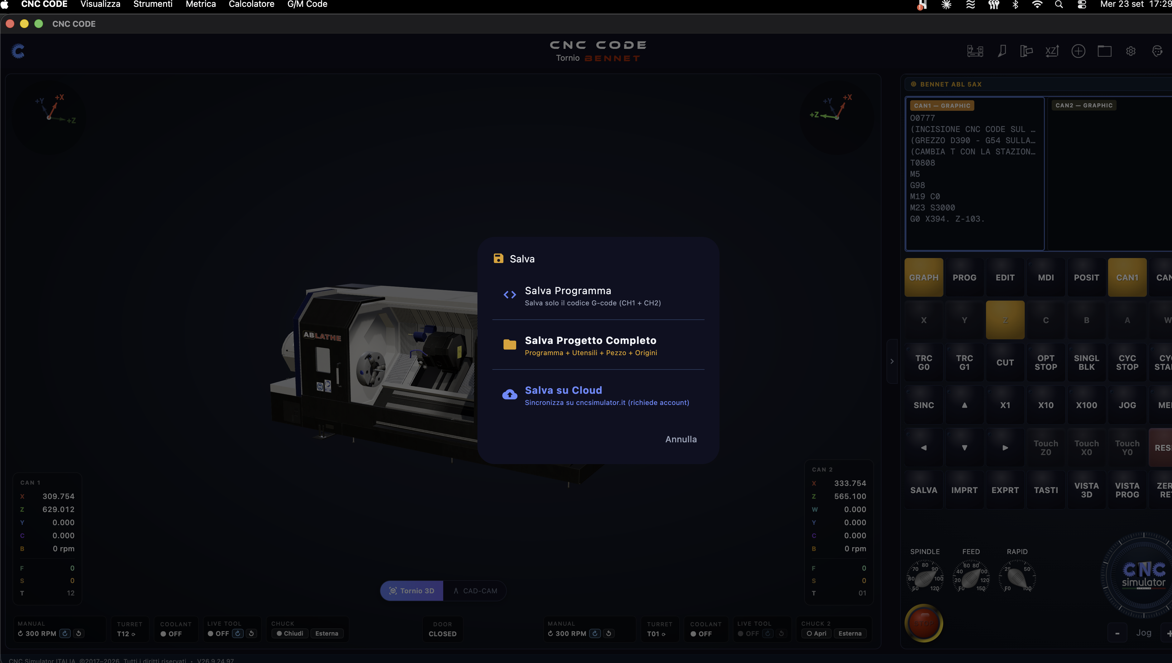
| Option | What is he asking for? |
|---|---|
| Save Program Only | A name for the file — save the code for both channels |
| Save the entire project | Name + a description — saves your entire workspace |
| Save to the Cloud | Save the project associated with your account; it can also be accessed from another device |
14.3 About the Milling Machine
On a milling machine, saving is simpler: there’s only the program (pure G-code). There is no equivalent to the lathe’s “complete project”—tools, blank workpiece, and origins are not saved along with the code. Give the program a name, and you’ll find it in the milling machine’s project list.
Open a Program
Every save has its own name—whether it's a regular program or a complete project, the result of opening it changes in a way that's consistent with what you saw in the previous chapter.
15.1 The IMPRT Button — Lathe
On the command keyboard, the IMPRT button opens a dialog box with five options:
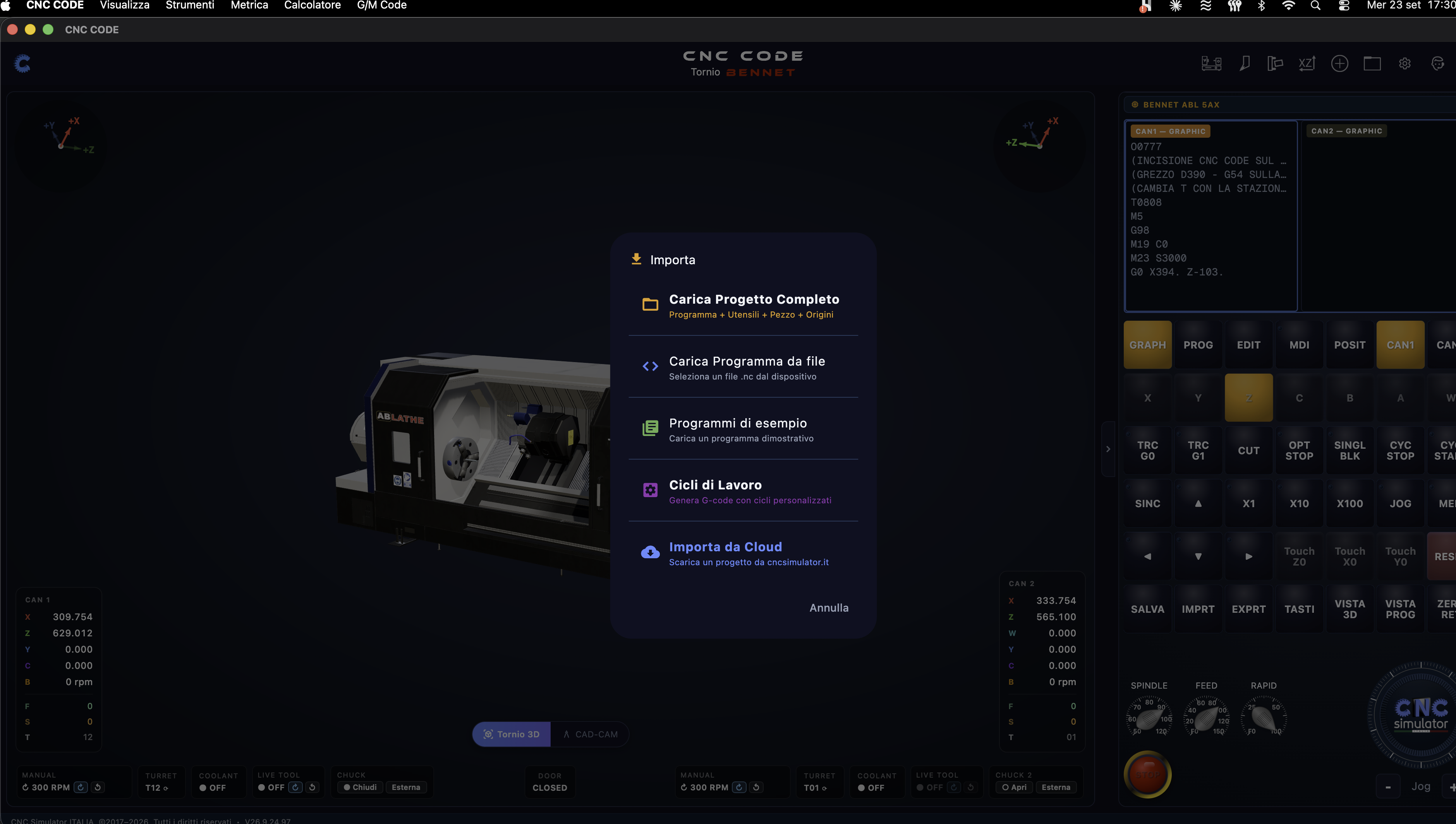
| Option | What does it do? |
|---|---|
| Upload the complete project | List of saved .cncproj projects — EVERYTHING reopens: code,
tools, blank files, origins—exactly as you left them |
| Load program from file only | Opens the operating system's file selection dialog — restores ONLY the code, without altering the current tools, blank data, or origins |
| Examples | A library of ready-to-use sample programs, useful for learning or quick practice |
| Work Cycles | A parametric wizard that generates G-code by guiding you step by step (not just a simple file call) |
| Import from the Cloud | List of projects saved to your account, which can also be opened on another device |
15.2 On the Milling Machine
Following the simplest save method (Chapter 14), load a program from the project list onto the mill: you’ll get only the G-code, which you can load into the editor as a starting point for your current project.
Exporting and Importing a Program
In addition to saving files within the app, you can import a program outside from CNC Code as a file, or import one created elsewhere. Useful for sharing a G-code file with a colleague, archiving it, or preparing it for a real machine.
16.1 Exporting a Program — Lathe
The EXPRT button on the control panel opens a dialog box with three options:
Channel 1 only, Channel 2 only, or both. The file is saved in
.nc format, with the filename automatically derived from the
program number (for example, O1234 becomes Programma_1234_CH1.nc).
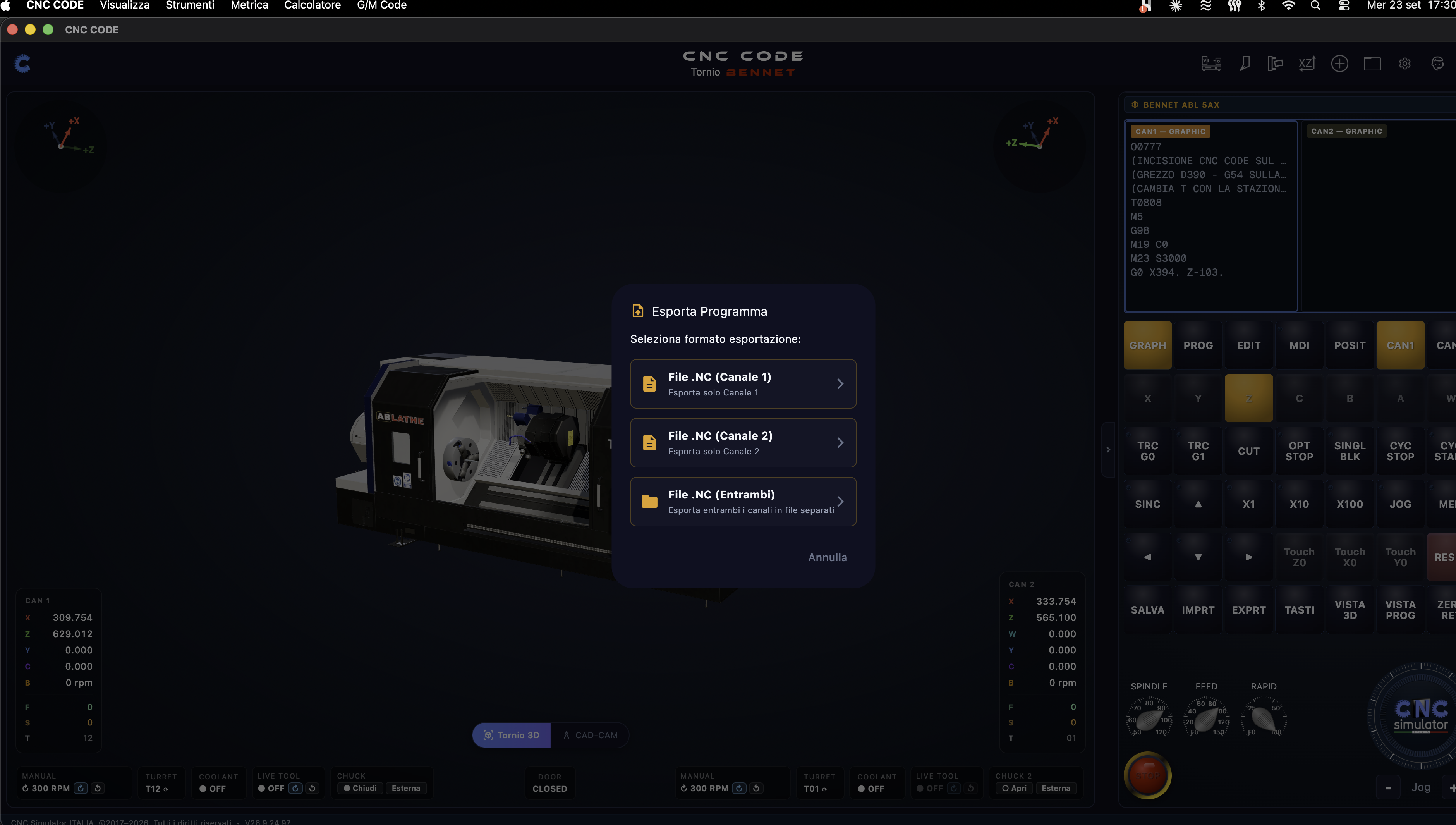
What happens next depends on the device:
| Platform | Behavior |
|---|---|
| macOS / Windows / Linux | The operating system's save panel opens so you can choose where to save the file |
| Web | The file starts as a browser download |
| Android | Select the destination folder (usually "Downloads"), with a notice displayed first |
| iOS | The system sharing dialog box opens |
For the complete project, the process is the same, but the exported file
is in the ".cncproj" format (it also contains tools, the blank, and
origins, as seen in Chapter 14).
16.2 Importing a Program — Lathe
In the IMPRT dialog (Chapter 15), the "Load program from file only" option opens the system's file selection dialog. CNC Code is intentionally flexible regarding the formats it accepts, so that it can also read files written by different real controls:
| Accepted file extensions |
|---|
| .nc · .txt · .cnc · .prg · .min · .tap · .mpf |
For the complete project, the import function accepts .cncproj files generated by the app, as well as plain .json files.
16.3 About the Milling Machine
.nc via the system’s file-sharing feature), but
importing from an external file is not available. This is not an oversight in the
manual: it is a real limitation of the current version of the app. If you have G-code written
elsewhere that you want to import into the milling machine, for now the only way is to copy the text and paste it
directly into the editor at EDIT.
G-Code Reference — TORNIO Lathe
The complete list of G codes actually implemented in the Fanuc interpreter of the lathe module—the reference implementation of CNC Code. Not all real controls support exactly this same syntax: use this table as a reference for the simulator, not as a substitute for your actual machine's manual.
17.1 Basic Movement
| Code | Syntax | Function | Example |
|---|---|---|---|
| G00 | G00 X.. Z.. | Rapid, non-contact motion | G00 X50. Z2. |
| G01 | G01 X.. Z.. F.. | Linear Interpolation in Practice | G01 X40. Z-20. F0.15 |
| G02 | G02 X.. Z.. R.. F.. | Time zone (CW) | G02 X30. Z-10. R5. F0.1 |
| G03 | G03 X.. Z.. R.. F.. | Counterclockwise (CCW) arc | G03 X30. Z-10. R5. F0.1 |
| G04 | G04 P.. (ms) or G04 X.. (sec) | Timed pause (dwell) | G04 P500 |
| G28 | G28 X.. / Z.. / U0 W0 / on my own | Return to machine reference, on the specified axis or on all axes | G28 U0 W0 |
| G30 | G30 P.. | Return to the nth reference position (default P2) | G30 P2 |
| G53 | G53 G0 X.. Z.. | Movement in machine coordinates; ignores the active workpiece origin (non-modal) | G53 G0 X200. Z50. |
| G31 | G31 Z.. F.. | Skip/Probe Function — Advances to the probe contact | G31 Z-50. F100 |
17.2 Coordinates, Units, Origins
| Code | Syntax | Function | Example |
|---|---|---|---|
| G20 | G20 | Units of measurement in inches | G20 |
| G21 | G21 | Unit of measurement in millimeters | G21 |
| G90 | G90 (by himself) | Absolute coordinates (modal) | G90 |
| G91 | G91 | Incremental coordinates (modal) | G91 |
| G17/G18/G19 | G17 / G18 / G19 | XY / ZX / YZ Working Plane Selection | G18 |
| G54–G59 | G54 … G59 | Activate the corresponding workpiece origin | G55 |
| G10 | G10 L2 P.. X.. Z.. | Set/update a workpiece origin (P1=G54 … P6=G59) from the program | G10 L2 P1 X0 Z300. |
| G68.1 | G68.1 I.. J.. K.. | Activate the tilted plane (rotation of the coordinate system) | G68.1 I0 J1 K0 |
| G69.1 | G69.1 | Cancel the tilted plane | G69.1 |
17.3 Spindle and Feed
| Code | Syntax | Function | Example |
|---|---|---|---|
| G96 | G96 S.. | Constant cutting speed (CSS), S in meters per minute | G96 S180 |
| G97 | G97 S.. | Constant spindle speed (direct RPM), cancels CSS | G97 S1200 |
| G98 | G98 | Feed rate (mm/min) | G98 |
| G99 | G99 | Feed per revolution (mm/rev) — typical for turning | G99 |
| G50 | G50 S.. | Maximum spindle speed | G50 S3000 |
G92 On its own, the term “S” has the same meaning as “limit”
spindle of G50 — but be careful: G92 with X/Z in the same row is something entirely
different; it refers to the single-pass threading cycle (see §17.7).
17.4 Tool Offset
| Code | Function |
|---|---|
| G40 | Clear the tool radius compensation |
| G41 | Tool radius compensation to the left of the profile |
| G42 | Tool radius compensation to the right of the profile |
| G43 / G49 | Accepted but ignored: On the lathe, length compensation is already handled by the tool table |
| G80 | Clear any active canned cycles (G71/G72/G73/G74/G75/G76/G83/G84/G85/G88/G89/System A) |
17.5 Roughing and Finishing Cycles (G70–G73)
The most powerful method for roughing a profile: simply define the finished profile between two sequences N, and the loop calculates all the necessary passes on its own. Complete syntax demonstrated in the example in Chapter 9.
| Code | Syntax | Function |
|---|---|---|
| G71 | Block 1: G71 U.. [R..] — Block 2: G71 P.. Q.. U.. W.. F.. (or a single line with D..) | Longitudinal roughing: U = radial depth per pass, R = retract, P/Q = sequences of the finished profile, U/W = finishing allowance |
| G72 | Block 1: G72 W.. [R..] — Block 2: identical to G71 | Roughing front (facing): Same as G71, but block 1 uses W (axial depth) instead of U |
| G73 | Block 1: G73 U.. W.. R.. — Block 2: identical to G71 | Roughing with a repeating pattern that follows the contour of the blank (useful for forged and cast parts); R = number of repetitions |
| G70 | G70 P.. Q.. | Finishing: Retrace the profile defined between the P/Q blocks of a previous G71/G72/G73 command at finishing speed |
Example: G71 with two blocks (as in Chapter 9):
G71 U2.0 R0.5
G71 P10 Q20 U0.3 W0.1 F0.15D instead of in
block 1: G71 P10 Q20 U0.3 W0.1 D2000 F0.15. The rule for D is: without a
decimal point, it is in microns (D2000 = 2 mm); with a decimal point, it is in
millimeters (D2.0). CNC Code accepts both forms.
17.6 Axial Drilling, Tapping, and Boring Cycles (Z-axis)
Everyone does two blocks: Block 1 consists only of the R pull-up level, followed by Block 2 with the final dimension.
| Code | Block 1 | Block 2 | Function |
|---|---|---|---|
| G74 | G74 R.. | G74 Z.. Q.. F.. | Drilling/axial cuts with partial chip removal (Q = cut depth) |
| G83 | G83 R.. | G83 Z.. Q.. F.. | Deep drilling with full retraction to the R plane at each pass (different from G74) |
| G81 | — | G81 Z.. R.. F.. (single line) | Simple drilling without chipping: rapid feed to R, feed to the bottom, rapid return |
| G84 | G84 R.. | G84 Z.. F.. | Synchronous axial tapping — F = thread pitch, automatic reversal at the bottom |
| G85 | G85 R.. | G85 Z.. F.. | Axial boring — feed in both the in-feed and out-feed directions |
Example G83:
G83 R2.
G83 Z-45. Q5000 F0.15
17.7 Radial Cycles on the Diameter (X-axis)
Same logic as axial cycles, but on the X-axis—workpiece oriented in C, motorized tool on the radial sub-spindle:
| Code | Block 1 | Block 2 | Function |
|---|---|---|---|
| G75 | G75 R.. | G75 X.. Z.. P.. Q.. F.. | Radial grooves on the diameter, including multiple grooves (Q = pitch between grooves) |
| G88 | G88 R.. | G88 X.. F.. | Radial tapping on the diameter (radial twin of G84) |
| G89 | G89 R.. | G89 X.. F.. | Radial boring on the diameter (radial twin of G85) |
G84 or G85 with an X instead of
a Z, the simulator flags the error and suggests G88/G89: these are
different cycles, not variations of the same line.
17.8 Threading
| Code | Syntax | Function |
|---|---|---|
| G32 | G32 Z.. F.. | Single-pass threading, manual (no automatic cycle) |
| G76 | Block 1: G76 P.. [Q..] [R..] — Block 2: G76 X|U.. Z|W.. P|K.. Q|D.. F|E.. [R|I..] [A..] | Automatic multi-pass threading cycle — words accepted in any order, whether in two blocks or on a single line (0T style) |
Classic G76 example (2×45° to 60°, 1.5 mm pitch):
G76 P010060 Q100 R0.05
G76 X47.62 Z-20. P1190 Q400 F1.5
In Block 1, "P010060
" is read in pairs: 01
= number of
finishing passes, 00
= retraction in tenths of a step, 60
= thread angle in degrees.
17.9 "System A" Cycles — G90, G92, G94 as Cycles
| Code | Syntax | Function |
|---|---|---|
| G90 (cycle) | G90 X.. Z.. [R..] F.. | Cylindrical/conical turning cycle — one complete pass (rapid, feed, return) |
| G92 (cycle) | G92 X.. Z.. F.. [R..] | A threading pass — a simplified version of G76; the R taper is read but not simulated |
| G94 (cycle) | G94 X.. Z.. [R..] F.. | Facing cycle — a full pass across the face |
Modal example (G90 repeated across multiple diameters without rewriting the code):
G90 X45. Z-30. F0.2
X40. Z-30.
X35. Z-30.
17.10 Special Cycle — Tsugami
| Code | Syntax | Function |
|---|---|---|
| G900 | G900 D.. Z.. S.. X.. T.. F.. W.. V.. R.. | Automatic bar reloading cycle — only on controls with a counter-spindle/through-bar design (Tsugami style) |
G-Code Reference — FRESA Milling Machine
The complete list of G-codes actually implemented in the Bennet interpreter (dialect Fanuc 0i-MD) of the milling machine module. The milling machine has configurable axes in addition to X/Y/Z: an optional 4th axis (default letter C, rotary table) and an optional 5th axis (default letter A, tilting head/cradle)—if the program uses a letter that is not configured on the active machine, the interpreter issues a warning without halting execution.
18.1 Motion
| Code | Syntax | Function | Example |
|---|---|---|---|
| G00 | G00 X.. Y.. Z.. | Rapid movement along the 3 axes | G00 X50. Y30. Z10. |
| G01 | G01 X.. Y.. Z.. F.. | Linear Interpolation in Practice | G01 X100. Y50. F300 |
| G02 | G02 X.. Y.. I.. J.. F.. (floor G17) or at R.. | Circular interpolation by hour — I/J = center relative to the starting point, R = radius (R > 0 for arcs ≤ 180°, R < 0 for arcs > 180°) | G02 X50. Y0 I-25. J0 F150 |
| G03 | such as G02 | Counterclockwise circular interpolation | G03 X0 Y25. I-25. J0 F150 |
| G04 | G04 P.. (ms) or G04 X../U.. (sec) | Timed dwell, maximum 600,000 ms | G04 P500 |
Arcs also work on planes G18 (with I/K) and G19 (with J/K), not just on G17.
18.2 Select Plane, Unit, Coordinates
| Code | Function |
|---|---|
| G17 | XY Working Plane (default, used for almost all machining operations) |
| G18 | ZX Floor |
| G19 | YZ Floor |
| G20 | Units of measurement in inches |
| G21 | Unit of measurement in millimeters (default) |
| G90 | Absolute coordinates (default) |
| G91 | Incremental coordinates |
18.3 Machine Returns and Workpiece Origins
| Code | Syntax | Function | Example |
|---|---|---|---|
| G28 | G28 o G28 X.. Y.. Z.. | Automatic return to machine zero (Z moves first, then X/Y); when using coordinates, it moves through an intermediate point | G28 Z0 |
| G53 | G53 X.. Y.. Z.. (single-line, non-modal) | Movement in absolute machine coordinates; ignores the active workpiece origin | G53 Z0 |
| G54–G59 | G54 … G59 | Select one of the 6 stored workpiece origins | G54 |
| G54.1 | G54.1 P.. (n 1–48) | Extended workpiece origins, beyond the 6 standard ones | G54.1 P12 |
| G92 | G92 X.. Y.. Z.. | Set the current origin so that the current position matches the specified coordinates | G92 X0 Y0 Z0 |
| G52 | G52 X.. Y.. Z.. | Local origin, combined with active G54-59 | G52 X10. Y5. |
| G68 / G69 | G68 X.. Y.. R.. / G69 | Rotation of the coordinate system on the XY plane by R degrees around a center; G69 cancels it | G68 X0 Y0 R45. ... G69 |
18.4 Tool Length and Radius Compensation
| Code | Syntax | Function | Example |
|---|---|---|---|
| G43 | G43 Z.. H.. | Positive length compensation, H register = tool Z offset | G43 Z50. H3 |
| G44 | G44 Z.. H.. | Negative Length Compensation | G44 Z50. H3 |
| G49 | G49 | Cancel length compensation | G49 |
| G40 | G40 | Cancel radius compensation | G40 |
| G41 | G41 D.. | Offset to the left of the feed direction, register D = tool radius | G41 D1 X50. Y0 |
| G42 | G42 D.. | Right-hand offset | G42 D1 X50. Y0 |
A complete practical example is provided in Chapter 10.
18.5 Feed and Spindle
| Code | Function |
|---|---|
| G94 | Feed rate per minute (default) |
| G95 | Feed per revolution |
| G96 | Constant Cutting Speed (CSS) |
| G97 | Constant RPM (default) |
| G98 | At the end of the canned cycle, it returns to the initial position (Z-dimension before the cycle) |
| G99 | At the end of a canned cycle, it returns to the R plan (default) |
18.6 Canned Drilling, Tapping, and Reaming Cycles
Active plane for XY, R = safety dimension, Z = dimension for the bottom of the hole, F = feed rate. Repeat only the XY position on subsequent lines to automatically repeat the active cycle (multiple drilling). Canceled by G80.
| Code | Syntax | Function | Example |
|---|---|---|---|
| G80 | G80 | Cancel the active canned cycle | G80 |
| G81 | G81 X.. Y.. Z.. R.. F.. | Simple Drilling: Rapid R, Z Feed, Rapid Return | G81 X20. Y20. Z-15. R2. F100 |
| G82 | G82 X.. Y.. Z.. R.. P.. F.. | Drilling with a dwell at the bottom (P in ms) before rapid retraction | G82 X20. Y20. Z-15. R2. P500 F100 |
| G83 | G83 X.. Y.. Z.. R.. Q.. F.. | Deep peck drilling with complete chip removal on every pass | G83 X20. Y20. Z-30. R2. Q5. F80 |
| G73 | G73 X.. Y.. Z.. R.. Q.. F.. | Drilling with chip breaking: short-retract feed (1 mm) | G73 X20. Y20. Z-30. R2. Q3. F100 |
| G84 | G84 X.. Y.. Z.. R.. F.. | Tapping: CW on the screw, CCW at the output (F = pitch × revolutions) | G84 X20. Y20. Z-15. R5. F125 |
| G74 | G74 X.. Y.. Z.. R.. F.. | Tapping on the left: CCW on the inlet, CW on the outlet | G74 X20. Y20. Z-15. R5. F125 |
| G85 | G85 X.. Y.. Z.. R.. F.. | Boring: Feed during both the in-feed and out-feed strokes | G85 X20. Y20. Z-15. R2. F80 |
| G86 | G86 X.. Y.. Z.. R.. F.. | Reaming: feed-in, spindle stops at the bottom, rapid retraction | G86 X20. Y20. Z-15. R2. F80 |
| G89 | G89 X.. Y.. Z.. R.. P.. F.. | Reaming with a dwell at the bottom (P in ms), followed by a feed exit | G89 X20. Y20. Z-15. R2. P300 F80 |
| G76 | G76 X.. Y.. Z.. R.. Q.. P.. F.. | Precision boring: feeds, dwells, spindle orientation, Q-axis movement along the diameter, rapid exit | G76 X20. Y20. Z-20. R2. Q0.3 F60 |
M Code Reference
The auxiliary functions (M) control everything other than motion: the spindle, coolant, tool change, end of program, and—on the lathe—collets, tailstock, C-axis, and synchronization between the two channels. The list is organized by machine type, because the codes implemented differ between lathes and milling machines.
19.1 M Codes — TORNIO Lathe
The lathe has two independent channels (turret1 = Channel 1, sub-spindle/turret2 = Channel 2): many codes related to the spindle, collets, powered tool, or coolant behave differently depending on which channel executes them—as indicated on a case-by-case basis.
Program Control
| Code | Syntax | Function | Example |
|---|---|---|---|
| M00 | M00 | Program stop, waiting for the operator (press CYC START to resume) | M00 |
| M01 | M01 | Optional stop — stops only if the OPT STOP switch is active | M01 |
| M02 | M02 | End of program: stops the spindle and the powered tool, closes the channel | M02 |
| M30 | M30 | End Program + Increment the counter for completed workpieces | M30 |
| M98 | M98 P.. [L..] | Calls a subprogram, repeated L times (default 1) | M98 P1002 L3 |
| M99 | M99 | Return from the subprogram (or end of cycle if inside a G7x) | M99 |
Spindle and counter-spindle
| Code | Syntax | Function | Example |
|---|---|---|---|
| M03 | M03 S.. | Horizontal spindle — channel 1 controls the main spindle, channel 2 controls the counter spindle | M03 S1500 |
| M04 | M04 S.. | Counterclockwise spindle, same channel logic as M03 | M04 S800 |
| M05 | M05 | Spindle stop (main spindle or sub-spindle, depending on the channel) | M05 |
| M19 | M19 [C..] | Spindle orientation; with C and without linear movement, orients to the specified absolute angle | M19 C0 |
| M20 | M20 | Resets the orientation set by M19 | M20 |
| M52 | M52 [S..] | Clockwise counter-spindle rotation | M52 S1200 |
| M53 | M53 [S..] | Counter-spindle rotation in the counterclockwise direction | M53 S1200 |
| M103 / M104 / M105 | M103 / M104 / M105 | CW/CCW/Stop Sub-Spindle (Direct Call, Independent of Channel) | M103 |
| M113 / M114 | M113 / M114 | CW/CCW Sub-Spindle + Coolant ON in a Single Operation | M113 |
Tool Change
| Code | Function | Example |
|---|---|---|
| M06 | On the lathe, it does nothing on its own: tool changing is already handled by the T command (T0101); M06 is accepted only for compatibility purposes | T0202 M06 |
Coolant
| Code | Function |
|---|---|
| M07 | Coolant (mist) ON |
| M08 | External Coolant (Full Flow) ON |
| M09 | The coolant shuts everything down (both M07 and M08) |
| M86 / M87 | Spindle Head Internal Coolant ON/OFF |
| M88 / M89 | Internal Coolant for Counter-Spindle ON / OFF |
| M108 / M109 | Counter-spindle Coolant ON/OFF (Direct Call) |
Collets and jaws
| Code | Function |
|---|---|
| M10 / M11 | Clamping/releasing the main spindle collet — only from channel 1 |
| M21 | Rear Chuck Release |
| M68 / M69 | Closing/opening the sub-spindle collet — only via channel 2 |
Powered tool (live tooling)
| Code | Function |
|---|---|
| M13 / M23 | CW Power Tool (Turret 1; controls Turret 2 from Channel 2) |
| M14 / M24 | CCW Power Tool |
| M15 / M25 | Powered Tool Stop |
| M203 / M204 / M205 | "Fanuc-style" variant of M13/M14/M15 |
| M123 / M124 / M125 | Secondary Powered Tool (Turret 2) CW / CCW / Stop (Direct Call) |
Tailstock, C-axis, B-axis
| Code | Function |
|---|---|
| M78 / M79 | Advance / retract the tailstock |
| M50 / M51 | Enable/disable the C-axis of the main spindle (interpolated milling/turning mode) |
| M54 / M55 | Enable / disable the C-axis of the sub-spindle |
| M80 / M81 | Lock / unlock the B-axis (swivel turret) |
Cabin doors, override, sensor, synchronization
| Code | Function |
|---|---|
| M84 / M85 | Opens/closes the cabin doors (visual simulation only) |
| M48 / M49 | Enable / Disable Feed Rate and Speed Overrides |
| M165 / M166 | Enable/disable the spindle head thermal sensor (simulation) |
| M500 / M501 | Start/end of synchronization wait between the two channels — the channel pauses until the other channel also reaches its M501 |
| M901 | Reset 5-axis configuration: deactivates the G68.1 tilted plane and the C-axis (main and sub-spindle), and resets the C-angle |
19.2 M Codes — FRESA Milling Machine
| Code | Category | Function | Example |
|---|---|---|---|
| M00 | Program | Scheduled stop; resumes with CYC START | M00 |
| M01 | Program | Optional stop (only if OPT STOP is enabled) | M01 |
| M02 | Program | End of program: stop spindle/feed/coolant, count the workpiece, rewind | M02 |
| M03 | Spindle | Clockwise (CW) spindle — with "S" never programmed, starts at 500 rpm with a notice | M03 S2000 |
| M04 | Spindle | Counterclockwise (CCW) spindle | M04 S1500 |
| M05 | Spindle | Spindle Stop | M05 |
| M06 | Tool | Tool change: moves to rapid feed, initiates the change, and mounts the current T-tool | T3 M06 |
| M07 | Coolant | Mist Coolant | M07 |
| M08 | Coolant | External Coolant (Jet) | M08 |
| M09 | Coolant | Coolant Off (Both) | M09 |
| M19 | Spindle | Spindle orientation (fixed angular position; also used internally by G76) | M19 |
| M30 | Program | Same as M02, with rewinding | M30 |
| M48 | Override | Restore the speed/feed rate overrides | M48 |
| M49 | Override | Disable overrides (locked at 100%) | M49 |
| M98 | Subprogram | Calls subprogram P, repeated L times (default 1) | M98 P1010 L3 |
| M99 | Subprogram | Return from a subprogram to the caller | M99 |
End of Documentation
You have reached the end of the CNC Code Desktop user guide.
Back to the Table of Contents